
Service Manual


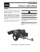


Table Of Contents
- Title Page
- Revision History
- Reader Comments
- Preface
- Table Of Contents
- 1 - Safety
- 2 - Product Records and Maintenance
- 3 - Engine
- Kohler Engine Service Manual
- 4 - Electrical System
- General Information
- Electrical Diagrams
- Special Tools
- Troubleshooting
- Electrical System Quick Checks
- Component Testing
- Ignition Switch
- Hour Meter
- Fuse
- Fusible Link
- Relays
- Remote Transmitter (Machines with Single Channel Controller
- Remote Transmitter (Machines with Multi Channel Controller)
- Wireless Control Module (Machines with Single Channel Controller)
- Wireless Control Module (Machines with Multi Channel Controller)
- Diode Assembly (Serial Number Below 310000000)
- Service and Repairs
- 5 - Blower Assembly
- 6 - Chassis
- 7 - Electrical Diagrams
- Electrical Schematic Model 44538 (S/N Below 310000000)
- Electrical Schematic Models 44538 and 44539 (S/N From 310000000 to 311999999) and Model 44542
- Electrical Schematic Models 44538 and 44539 (S/N Above 312000000)
- Engine Electrical Diagram (S/N Below 310000000)
- Engine Electrical Diagram (S/N Above 310000000)
- Control Module Wake Up
- Crank Circuits
- Run Circuits
- Engine Speed Increase Circuits
- Nozzle Rotation Circuits
- Wire Harness Drawing Model 44538 (S/N Below 310000000)
- Wire Harness Diagram Model 44538 (S/N Below 310000000)
- Wire Harness Drawing Models 44538 and 44539 (S/N 310000000 to 311999999) and Model 44542
- Wire Harness Diagram Models 44538 and 44539 (S/N 310000000 to 311999999) and Model 44542
- Wire Harness Drawing Models 44538 and 44539 (S/N Above 312000000)
- Wire Harness Diagram Models 44538 and 44539 (S/N Above 312000000)

Rev. C
ProForce Debris Blower
Table Of Contents
Chapter 1 - Safety
Safety Instructions 1 - 2..........................
Securing ProForce Debris Blower to Tow Vehicle 1 - 5
Jacking Instructions 1 - 5.........................
Safety and Instruction Decals 1 - 6................
Chapter 2 - Product Records and Maintenance
Product Records 2 - 1...........................
Maintenance 2 - 1...............................
Equivalents and Conversions 2 - 2................
Torque Specifications 2 - 3.......................
Chapter 3 - Engine
Specifications 3 - 2..............................
General Information 3 - 3........................
Service and Repairs 3 - 5........................
KOHLER COMMAND ENGINE SERVICE MANUAL
Chapter 4 - Electrical System
General Information 4 - 2........................
Electrical Diagrams 4 - 2.........................
Special Tools 4 - 3..............................
T roubleshooting 4 - 5............................
Electrical System Quick Checks 4 - 8..............
Component Testing 4 - 9.........................
Service and Repairs 4 - 20.......................
Chapter 5 - Blower Assembly
General Information 5 - 2........................
Special Tools 5 - 3..............................
Service and Repairs 5 - 4........................
Chapter 6 - Chassis
Specifications 6 - 2..............................
General Information 6 - 3........................
Service and Repairs 6 - 4........................
Chapter 7 - Electrical Diagrams
Electrical Schematics 7 - 3.......................
Engine Electrical Diagrams 7 - 6..................
Circuit Drawings 7 - 8............................
Wire Harness Drawings 7 - 14....................
SafetyProduct Records
and Maintenance
EngineElectricalBlower
System
Chassis
Assembly
Electrical
Diagrams