
Service Manual
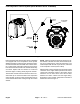


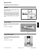
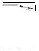
Table Of Contents
- Title Page
- Revision History
- Reader Comments
- Preface
- Table Of Contents
- 1 - Safety
- 2 - Product Records and Maintenance
- 3 - Engine
- Kohler Engine Service Manual
- 4 - Electrical System
- General Information
- Electrical Diagrams
- Special Tools
- Troubleshooting
- Electrical System Quick Checks
- Component Testing
- Ignition Switch
- Hour Meter
- Fuse
- Fusible Link
- Relays
- Remote Transmitter (Machines with Single Channel Controller
- Remote Transmitter (Machines with Multi Channel Controller)
- Wireless Control Module (Machines with Single Channel Controller)
- Wireless Control Module (Machines with Multi Channel Controller)
- Diode Assembly (Serial Number Below 310000000)
- Service and Repairs
- 5 - Blower Assembly
- 6 - Chassis
- 7 - Electrical Diagrams
- Electrical Schematic Model 44538 (S/N Below 310000000)
- Electrical Schematic Models 44538 and 44539 (S/N From 310000000 to 311999999) and Model 44542
- Electrical Schematic Models 44538 and 44539 (S/N Above 312000000)
- Engine Electrical Diagram (S/N Below 310000000)
- Engine Electrical Diagram (S/N Above 310000000)
- Control Module Wake Up
- Crank Circuits
- Run Circuits
- Engine Speed Increase Circuits
- Nozzle Rotation Circuits
- Wire Harness Drawing Model 44538 (S/N Below 310000000)
- Wire Harness Diagram Model 44538 (S/N Below 310000000)
- Wire Harness Drawing Models 44538 and 44539 (S/N 310000000 to 311999999) and Model 44542
- Wire Harness Diagram Models 44538 and 44539 (S/N 310000000 to 311999999) and Model 44542
- Wire Harness Drawing Models 44538 and 44539 (S/N Above 312000000)
- Wire Harness Diagram Models 44538 and 44539 (S/N Above 312000000)
Rev. C
ProForce Debris BlowerPage 3 -- 12Engine
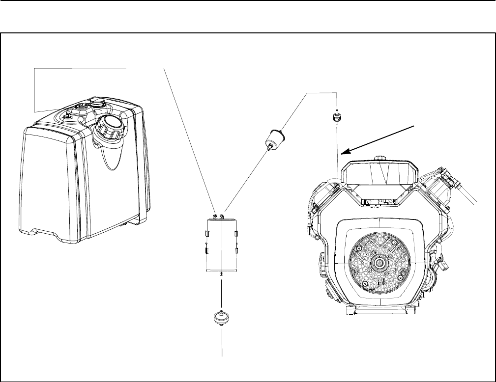
Fuel Evaporative Control System (Serial Number Above 310000000)
Figure 11
FRESH AIR
FILTER
CARBON
CANISTER
FUEL
TANK
ENGINE
CHECK
VALVE
TO ENGINE
FITTING
FILTER
ProForce blowers with serial number above 310000000
are equipped with a fuel evaporative control system
(EVAP) designed to collect and store evaporative emis-
sions from the fuel tank. The EVAP uses a carbon canis-
ter to collect these evaporative emissions. Fuel vapors
from the fuel tank are vented to the canister where they
are stored. Vapors from the canister are consumed
when the engine is running which purges the canister.
The fuel tank on these ProForce machines uses a non--
vented fuel cap. To connect the tank to the evaporative
control system, a fuel vent valve is positioned in the top
of the tank that allows tank venting through the carbon
canister.
NOTE: If there is restriction in the fresh air filter, the car-
bon canister or the fuel vent valve, the fuel tank may dis-
tort due to venting issues. If the fuel tank returns to it’s
normal shape when the fuel cap is removed, restriction
in the evaporative control system is likely.
Machines with a carbon canister include a single engine
connection to the engine intake system that is used to
connect the evaporative system to the engine. These
machines use an inline check valve and fuel filter
between the carbon canister and the engine fitting.
Evaporative control system components for ProForce
blowers are shown in Figure 11.