
Service Manual


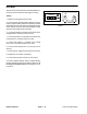
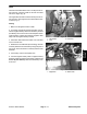
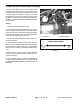
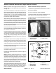
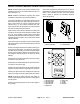
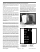
Table Of Contents
- Title Page
- Revision History
- Reader Comments
- Preface
- Table Of Contents
- 1 - Safety
- 2 - Product Records and Maintenance
- 3 - Engine
- Kohler Engine Service Manual
- 4 - Electrical System
- General Information
- Electrical Diagrams
- Special Tools
- Troubleshooting
- Electrical System Quick Checks
- Component Testing
- Ignition Switch
- Hour Meter
- Fuse
- Fusible Link
- Relays
- Remote Transmitter (Machines with Single Channel Controller
- Remote Transmitter (Machines with Multi Channel Controller)
- Wireless Control Module (Machines with Single Channel Controller)
- Wireless Control Module (Machines with Multi Channel Controller)
- Diode Assembly (Serial Number Below 310000000)
- Service and Repairs
- 5 - Blower Assembly
- 6 - Chassis
- 7 - Electrical Diagrams
- Electrical Schematic Model 44538 (S/N Below 310000000)
- Electrical Schematic Models 44538 and 44539 (S/N From 310000000 to 311999999) and Model 44542
- Electrical Schematic Models 44538 and 44539 (S/N Above 312000000)
- Engine Electrical Diagram (S/N Below 310000000)
- Engine Electrical Diagram (S/N Above 310000000)
- Control Module Wake Up
- Crank Circuits
- Run Circuits
- Engine Speed Increase Circuits
- Nozzle Rotation Circuits
- Wire Harness Drawing Model 44538 (S/N Below 310000000)
- Wire Harness Diagram Model 44538 (S/N Below 310000000)
- Wire Harness Drawing Models 44538 and 44539 (S/N 310000000 to 311999999) and Model 44542
- Wire Harness Diagram Models 44538 and 44539 (S/N 310000000 to 311999999) and Model 44542
- Wire Harness Drawing Models 44538 and 44539 (S/N Above 312000000)
- Wire Harness Diagram Models 44538 and 44539 (S/N Above 312000000)
Rev. B
ProForce Debris Blower
Page 4 -- 12
Electrical System
Fusible Link (Serial Number Below 310000000)
ProForce Debris Blowers with a serial number below
310000000 use a fusible link for circuit protection. This
fusible link connects the main wire harness to the starter
B+ terminal and positive battery cable (Fig. 12). If the
link should fail, current to the machine will cease. Refer
to electrical schematic and wire harness drawings in
Chapter 7 -- Electrical Diagrams for additional fusible
link information.
Testing
1. Make sure that ignition switch is OFF.
2. To prevent unexpected machine operation, discon-
nect the negative battery cable from the battery terminal
(see Battery Service in the Service and Repairs section
of this chapter). Position disconnected negative cable
away from the negative battery terminal.
3. Locate and unplug fusible link connector from ma-
chine wire harness.
4. Use a multimeter to make sure that continuity exists
between the disconnected fusible link connector and the
link terminal at the starter motor (Fig. 13). If the fusible
link is open (no continuity), replace the fusible link har-
ness.
5. After testing is complete, make sure that fusible link
connectors are securely attached to starter and ma-
chine wire harness.
6. Connect negative battery cable to negative battery
terminal. Tighten nut that secures battery cable from 10
to 15 ft--lb (14 to 20 N--m). Make sure that battery cover
is secured.
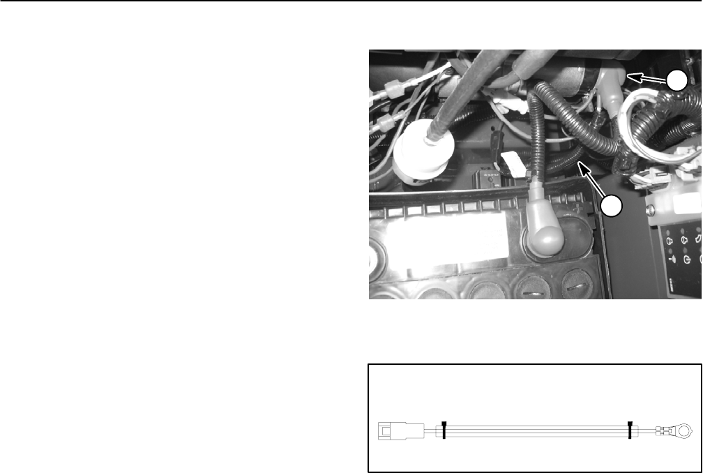
1. Fusible link
2. Starter B+ terminal
Figure 12
1
2
Figure 13
P1 J1
BATTERY B+HARNESS
FUSIBLE LINK HARNESS