
Service Manual
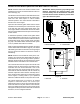
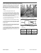

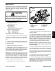
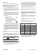
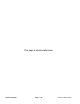
Table Of Contents
- Title Page
- Revision History
- Reader Comments
- Preface
- Table Of Contents
- 1 - Safety
- 2 - Product Records and Maintenance
- 3 - Engine
- Kohler Engine Service Manual
- 4 - Electrical System
- General Information
- Electrical Diagrams
- Special Tools
- Troubleshooting
- Electrical System Quick Checks
- Component Testing
- Ignition Switch
- Hour Meter
- Fuse
- Fusible Link
- Relays
- Remote Transmitter (Machines with Single Channel Controller
- Remote Transmitter (Machines with Multi Channel Controller)
- Wireless Control Module (Machines with Single Channel Controller)
- Wireless Control Module (Machines with Multi Channel Controller)
- Diode Assembly (Serial Number Below 310000000)
- Service and Repairs
- 5 - Blower Assembly
- 6 - Chassis
- 7 - Electrical Diagrams
- Electrical Schematic Model 44538 (S/N Below 310000000)
- Electrical Schematic Models 44538 and 44539 (S/N From 310000000 to 311999999) and Model 44542
- Electrical Schematic Models 44538 and 44539 (S/N Above 312000000)
- Engine Electrical Diagram (S/N Below 310000000)
- Engine Electrical Diagram (S/N Above 310000000)
- Control Module Wake Up
- Crank Circuits
- Run Circuits
- Engine Speed Increase Circuits
- Nozzle Rotation Circuits
- Wire Harness Drawing Model 44538 (S/N Below 310000000)
- Wire Harness Diagram Model 44538 (S/N Below 310000000)
- Wire Harness Drawing Models 44538 and 44539 (S/N 310000000 to 311999999) and Model 44542
- Wire Harness Diagram Models 44538 and 44539 (S/N 310000000 to 311999999) and Model 44542
- Wire Harness Drawing Models 44538 and 44539 (S/N Above 312000000)
- Wire Harness Diagram Models 44538 and 44539 (S/N Above 312000000)
Rev. C
ProForce Debris Blower Page 4 -- 17 Electrical System
Wireless Control Module (Machines with Multi Channel Controller)
NOTE: Machines with a multi channel controller can be
identified by the lack of an external antenna on the con-
trol module (Fig. 21).
The wireless control module is a solid state electrical de-
vice that receives signal inputs from the remote trans-
mitter and uses those inputs to control machine
electrical operation. The control module is attached to
the frame next to the engine.
Inputs from the machine ignition switch and the remote
transmitter are monitored by the control module. Output
to the fuel relay, start relay, engine starter motor sole-
noid, engine throttle control module and nozzle rotation
relays are controlled based on the inputs received by the
control module.
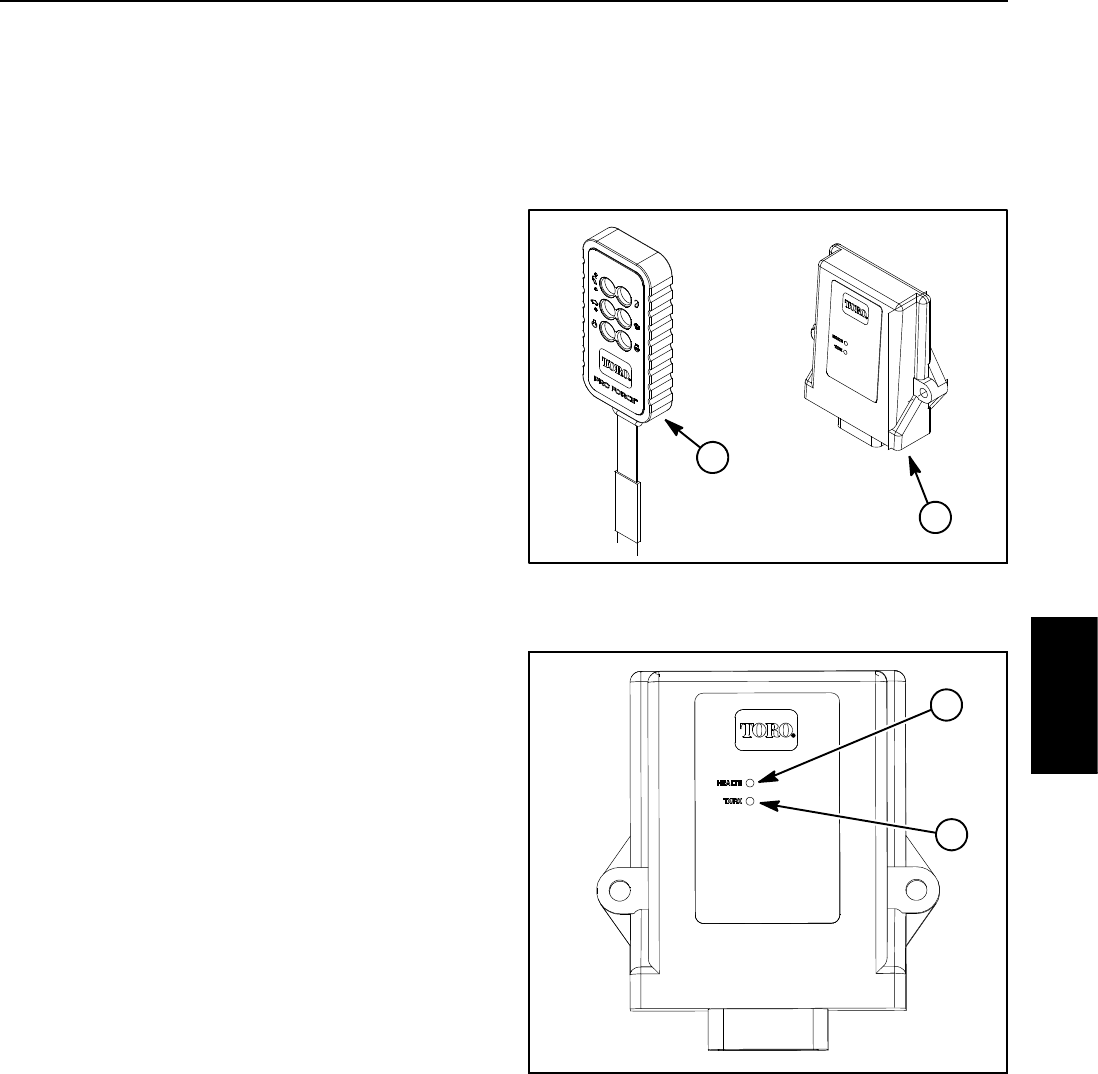
To start blower operation, rotation of the ignition switch
totheSTARTpositionisusedtoturnonor“wakeup”the
control module. The control module Health LED should
be illuminated green during normal blower operation
(Fig. 22). If the Health LED is illuminated either yellow
or red, a problem exists with the controller.
When a remote transmitter button is pressed, the control
module TX/RX LED should flicker (Fig. 22). The TX/RX
LED will be green when the module is receiving a signal
from the remote and will be red when the module is
transmitting.
NOTE: Because of the normal RF activity in the e nvi-
ronment, the control module TX/RX LED may flicker or
be illuminated at any time during machine operation.
Machine operation will only be controlled by the remote
transmitter that is associated to the control module.
The control module includes a power save mode if the
module is active for more than 2.5 hours without com-
munication from the remote transmitter. Once in the
power save mode, the control module will not commu-
nicate with the remote transmitter, will not activate any
machine outputs and will not function normally. All ma-
chine electrical power will be shut--off including turning
off the engine, if running. Refer to your Operator’s
Manual for additional details on the power save mode.
The control module does not connect to an external
computer or hand held device, can not be re--pro-
grammed and does not record any fault data. Because
of the solid state circuitry built into the control module,
there is no reliable method to test it. The module may be
damaged if an attempt is made to test it with an electrical
test device, such as a digital multimeter.
IMPORTANT: Before performing any welding on the
machine, disconnect the negative battery cable
from the battery and the wire harness connector
from the wireless control module to prevent dam-
age to the electrical system.
1. Remote transmitter
2. Control module
Figure 21
2
1
1. Health LED
2. TX/RX LED
Figure 22
1
2
Electrical
System