
Service Manual
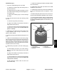
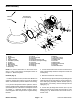
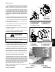

Table Of Contents
- Title Page
- Revision History
- Reader Comments
- Preface
- Table Of Contents
- 1 - Safety
- 2 - Product Records and Maintenance
- 3 - Engine
- Kohler Engine Service Manual
- 4 - Electrical System
- General Information
- Electrical Diagrams
- Special Tools
- Troubleshooting
- Electrical System Quick Checks
- Component Testing
- Ignition Switch
- Hour Meter
- Fuse
- Fusible Link
- Relays
- Remote Transmitter (Machines with Single Channel Controller
- Remote Transmitter (Machines with Multi Channel Controller)
- Wireless Control Module (Machines with Single Channel Controller)
- Wireless Control Module (Machines with Multi Channel Controller)
- Diode Assembly (Serial Number Below 310000000)
- Service and Repairs
- 5 - Blower Assembly
- 6 - Chassis
- 7 - Electrical Diagrams
- Electrical Schematic Model 44538 (S/N Below 310000000)
- Electrical Schematic Models 44538 and 44539 (S/N From 310000000 to 311999999) and Model 44542
- Electrical Schematic Models 44538 and 44539 (S/N Above 312000000)
- Engine Electrical Diagram (S/N Below 310000000)
- Engine Electrical Diagram (S/N Above 310000000)
- Control Module Wake Up
- Crank Circuits
- Run Circuits
- Engine Speed Increase Circuits
- Nozzle Rotation Circuits
- Wire Harness Drawing Model 44538 (S/N Below 310000000)
- Wire Harness Diagram Model 44538 (S/N Below 310000000)
- Wire Harness Drawing Models 44538 and 44539 (S/N 310000000 to 311999999) and Model 44542
- Wire Harness Diagram Models 44538 and 44539 (S/N 310000000 to 311999999) and Model 44542
- Wire Harness Drawing Models 44538 and 44539 (S/N Above 312000000)
- Wire Harness Diagram Models 44538 and 44539 (S/N Above 312000000)
Rev. C
ProForce Debris BlowerPage 5 -- 14Blower Assembly
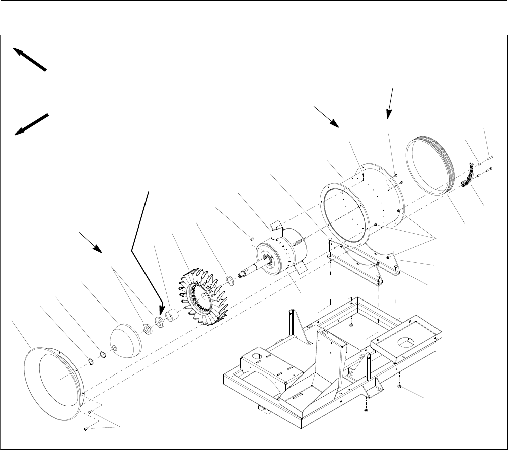
Inner Housing Assembly
1. Inlet bell
2. Retaining ring
3. Wave washer (up to 3 used)
4. Front cap
5. Nut (LH thread)
6. Spacer
7. Rotor assembly
8. Washer (as needed)
9. Woodruff key
10. Stator vane (24 used)
11. Carriage screw (2 used)
12. Outer housing
13. Flange head screw (24 used)
14. Cap screw (8 used)
15. Flange head screw (8 used)
16. Nozzle pulley
17. Cap screw (2 used per guide)
18. Nozzle guide (4 used)
19. Flange nut (16 used)
20. Fan housing mount (2 used)
21. Carriage screw (2 used)
22. Flange nut (4 used)
23. Inner housing assembly
24. Spacer (2 used per guide)
Figure 13
1
14
3
2
4
5
6
7
12
9
10
11
8
13
15
16
18
19
17
20
21
FRONT
RIGHT
Loctite #242
22
23
24
tightening
procedure
10 to 20 in--lb
(1.2 to 2.2 N--m)
90 to 100 in--lb
(10.2 to 11.2 N--m)
See text for
SERIAL NUMBER BELOW 310000000 SHOWN
NOTE: The rotor shaft and bearings can be serviced
without removing inner housing (item 23) from machine
(see Rotor Shaft in this section). For replacement of the
inner housing, stator vanes (item 10) or outer housing
(item 12), the following procedure is necessary.
NOTE: ProForce Blowers have used t hree (3) methods
of securing the inner and outer housings. On machines
with serial number below 310000000 (Fig. 13), the inner
housing is attached directly to the outer h ousing. On ma -
chines with serial number from 310000000 to
313000000, a fin spacer and possibly additional thin
spacers exist between the inner housing flanges and the
outer housing (Fig. 14). Machines with serial number
above 313000000 use four (4) fin mounts with fin
spacers and possibly additional thin spacers that are se-
cured b etween inner housing and outer housing (Fig.
15). Refer to correct illustration when removing and in -
stalling inner and outer housings.