
Service Manual
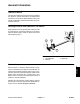
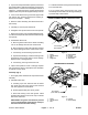
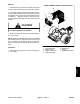
Table Of Contents
- Title Page
- Revision History
- Reader Comments
- Preface
- Table Of Contents
- 1 - Safety
- 2 - Product Records and Maintenance
- 3 - Engine
- Kohler Engine Service Manual
- 4 - Electrical System
- General Information
- Electrical Diagrams
- Special Tools
- Troubleshooting
- Electrical System Quick Checks
- Component Testing
- Ignition Switch
- Hour Meter
- Fuse
- Fusible Link
- Relays
- Remote Transmitter (Machines with Single Channel Controller
- Remote Transmitter (Machines with Multi Channel Controller)
- Wireless Control Module (Machines with Single Channel Controller)
- Wireless Control Module (Machines with Multi Channel Controller)
- Diode Assembly (Serial Number Below 310000000)
- Service and Repairs
- 5 - Blower Assembly
- 6 - Chassis
- 7 - Electrical Diagrams
- Electrical Schematic Model 44538 (S/N Below 310000000)
- Electrical Schematic Models 44538 and 44539 (S/N From 310000000 to 311999999) and Model 44542
- Electrical Schematic Models 44538 and 44539 (S/N Above 312000000)
- Engine Electrical Diagram (S/N Below 310000000)
- Engine Electrical Diagram (S/N Above 310000000)
- Control Module Wake Up
- Crank Circuits
- Run Circuits
- Engine Speed Increase Circuits
- Nozzle Rotation Circuits
- Wire Harness Drawing Model 44538 (S/N Below 310000000)
- Wire Harness Diagram Model 44538 (S/N Below 310000000)
- Wire Harness Drawing Models 44538 and 44539 (S/N 310000000 to 311999999) and Model 44542
- Wire Harness Diagram Models 44538 and 44539 (S/N 310000000 to 311999999) and Model 44542
- Wire Harness Drawing Models 44538 and 44539 (S/N Above 312000000)
- Wire Harness Diagram Models 44538 and 44539 (S/N Above 312000000)
ProForce Debris Blower Page 6 -- 3 Chassis
General Information
Operator’s Manual
The Operator’s Manual provides information regarding
the operation, general maintenance and maintenance
intervals for your ProForce Debris Blower. Refer to the
Operator’s Manual for additional information when ser-
vicing the machine.
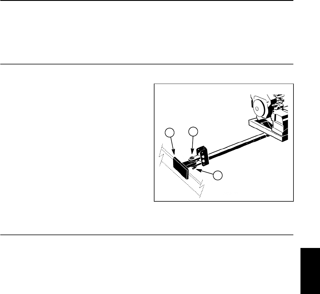
Securing ProForce Debris Blower to Tow Vehicle
While operating or servicing the ProForce blower, make
sure that hitch pin is properly positioned in tow vehicle
hitch and blower tongue. Hitch pin should be secured
with hairpin clip (Fig. 1).
1. Tow vehicle hitch
2. Hitch pin
3. Hairpin clip
Figure 1
3
2
1
Electrical Power
Electrical power to ProForce Debris Blower compo-
nents is c ontrolled by the Remote Control Module. To
make sure that machine operation does not occur unex-
pectedly, disconnect the negative battery cable from the
battery before performing any machine service (see
Battery Service in the Service and Repairs section of
Chapter 4 -- Electrical System).
Reattach the disconnected negative battery cable as
the last step in any repair. Secure cable with flange nut.
Torque nut from 10 to 15 ft--lb (14 to 20 N--m).
Chassis