
Operator's Manual

3
MountingtheHitchtothe
DebrisBlower
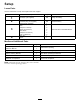
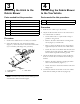
Partsneededforthisprocedure:
1Debrisblowerassembly
1Hitch
2
Bolt(3/8x3inches)
2
Flangenut(3/8inch)
1Hitchclevis
2
Bolt(5/8x4–1/2inch)
2
Locknut(5/8inch)
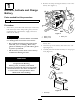
Procedure
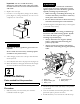
1.Positionthedebrisbloweronaat,levelsurface.
2.Insertthehitchtubeintotheframebrackets
(Figure7).Securethetubetotheframewith2bolts
(3/8x3inches)andangenuts(3/8inch).
Figure7
1.Framebrackets3.Hitchclevis
2.Hitchtube
Note:Thehitchtubecanberotated180degreesto
accommodatedifferenthitchheights.
4
ConnectingtheDebrisBlower
totheTowVehicle
Partsneededforthisprocedure:
1Hitchpin
1
Clevis
Procedure
1.Backthetowvehicleuptotheblower.
2.Adjusttheblowerhitchclevistothesamelevelas
towvehiclehitchasfollows:
•Setthehitchtubeonajackstandtokeepit
paralleltotheground.
•Removetheboltsandlocknutssecuringhitch
clevis(
Figure7)tohitchtube.
•Raiseorlowerthehitchclevistotheposition
approximatelylevelwiththetowvehiclehitch.
•Securetheclevistothehitchwiththeboltsand
locknutspreviouslyremoved.Makesuredebris
blowerframeisparallelwiththeground.
3.Adjustthehitchtubelengthtoassuretheblower
doesnotcontactthetowvehiclewhenturningas
follows:
•Removetheboltsandnutssecuringthehitch
tubetoframebrackets(
Figure7).
•Securethetubetotheframewiththeboltsand
angenuts.
4.Connecttheblowerclevishitchtothetowvehicle
hitchwiththehitchpinandclevis(
Figure8).
10