
Service Manual


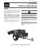


Table Of Contents
- Title Page
- Revision History
- Reader Comments
- Preface
- Table Of Contents
- 1 - Safety
- 2 - Product Records and Maintenance
- 3 - Engine
- Kohler Engine Service Manual
- 4 - Electrical System
- General Information
- Electrical Diagrams
- Special Tools
- Troubleshooting
- Electrical System Quick Checks
- Component Testing
- Ignition Switch
- Hour Meter
- Fuse
- Fusible Link
- Relays
- Remote Transmitter (Machines with Single Channel Controller
- Remote Transmitter (Machines with Multi Channel Controller)
- Wireless Control Module (Machines with Single Channel Controller)
- Wireless Control Module (Machines with Multi Channel Controller)
- Diode Assembly (Serial Number Below 310000000)
- Service and Repairs
- 5 - Blower Assembly
- 6 - Chassis
- 7 - Electrical Diagrams
- Electrical Schematic Model 44538 (S/N Below 310000000)
- Electrical Schematic Models 44538 and 44539 (S/N From 310000000 to 311999999) and Model 44542
- Electrical Schematic Models 44538 and 44539 (S/N Above 312000000)
- Engine Electrical Diagram (S/N Below 310000000)
- Engine Electrical Diagram (S/N Above 310000000)
- Control Module Wake Up
- Crank Circuits
- Run Circuits
- Engine Speed Increase Circuits
- Nozzle Rotation Circuits
- Wire Harness Drawing Model 44538 (S/N Below 310000000)
- Wire Harness Diagram Model 44538 (S/N Below 310000000)
- Wire Harness Drawing Models 44538 and 44539 (S/N 310000000 to 311999999) and Model 44542
- Wire Harness Diagram Models 44538 and 44539 (S/N 310000000 to 311999999) and Model 44542
- Wire Harness Drawing Models 44538 and 44539 (S/N Above 312000000)
- Wire Harness Diagram Models 44538 and 44539 (S/N Above 312000000)

Part No. 08158SL (Rev. D)
Service Manual
ProForce
R
Debris Blower
Preface
The purpose of this publication is to provide the service
technician with information for troubleshooting, testing
and repair of major systems and components on the
ProForce Debris Blower.
REFER TO THE OPERATOR’S MANUALS FOR OP-
ERATING, MAINTENANCE AND ADJUSTMENT
INSTRUCTIONS. Space is provided in Chapter 2 of this
book to insert the Operator’s Manuals and Parts Cata-
logs for your machine. Additional copies of the Opera-
tor’ s Manual are available on the Internet at
www.Toro.com.
The Toro Company reserves the right to change product
specifications or this publication without notice.
This safety symbol means DANGER, WARNING,
or CAUTION, PERSONAL SAFETY INSTRUC-
TION. When you see this symbol, carefully read
the instructions that follow. Failure to obey the
instructions may result in personal injury.
NOTE: A NOTE will give general information about the
correct operation, maintenance, service, testing or re-
pair of the machine.
IMPORTANT: The IMPORTANT notice will give im-
portant instructions which must be followed to pre-
vent damage to systems or components on the
machine.
EThe Toro Company -- 2008, 2009, 2011,
2014, 2018