
Installation Instructions


G014241
1 2 3
4
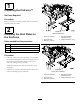
Figure6
1.Flangenut(3/8inch)3.Carriagebolt(3/8x2
inches)
2.Lockingplate4.Lockingplateassembly
6
InstallingtheProForceon
UniversalVehicles
Partsneededforthisprocedure:
Purchasecorrecthardware
Procedure
Foruniversalvehicles,youwillneedtopurchasethe
correcthardwaretofastentheProForcetothevehicle.
AdjustthepositionoftheProForcetoallowthenozzle
torotatewithouthittingthebed.Usingtherearholes,
markanddrillholesintothebedandfastentheProForce
tothebedofthevehicle.
7
InstallingtheExtension
Partsneededforthisprocedure:
1Positionindicator
3Rivot
2
Chutebracket
4
Carriagebolt(10-24x5/8inches)
2Nozzlemount
4
Locknut(10-24)
2Hitchpin
10
Flangenut(1/4inch)
2Extensionshell
2Nozzlekeel
10
Bolt(1/4x3/4inches)
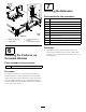
Procedure
1.Assemblethetwoextensionshellsandthetwo
nozzlekeelsinbetweentheextensionshellswith
10bolts(1/4x3/4inches)and10angenuts(1/4
inch)(
Figure7).
5