
Installation Instructions
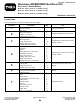


G015436
1
2
3
1
4
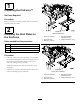
Figure7
1.Extensionshells3.Nozzlekeel
2.Bolt(1/4x3/4inches)4.Flangenut(1/4inch)
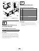
2.For2010andoldermachines,drillthefour1/4inch
holesshowninFigure8forthechutebrackets.
G014243
1
1
2
2
3
Figure8
1.1-1/8inches(28.5mm)3.Drill1/4inchholes(4)
2.3-1/4inches(82.5mm)
3.For2010andoldermachines,drillthethree1/4inch
holesshowninFigure9forthepositionindicator.
4.Installthepositionindicatorwiththe3rivots
(
Figure10).
6