
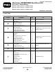
Installation Instructions


1
2
3
4
5
5
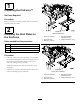
G014240
Figure9
1.4-3/8inches(111mm)4.Drill1/4inchhole
2.Drill1/4inchhole
5.55degrees
3.4-3/4inches(120.6mm)
5.Looselyinstallbothchutebracketstothenozzle
with4carriagebolts(10–24x5/8inches),2nozzle
mountsand4locknuts(10-24)(Figure10).
6.Installtheextensionontothenozzleandattachit
withthehitchpins.Tightenthechutebracketsonce
theextensionisinstalled(Figure10).
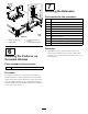
1
2
3 4 5
6
7
8
G014242
Figure10
1.Rivot5.Hitchpin
2.Positioninditcator
6.Carriagebolt(10-24)
3.Chutebracket
7.Nozzlemount
4.Locknut(10-24)
8.Nozzleextension
7