Form No.
Revision History Revision Date -- 2014 A 02/2018 Added revision history. B 06/2020 Updated Electrical chapter. © THE TORO COMPANY 2020 Description Initial Issue. This document and all information contained herein is the sole property of The Toro Company (and/or its affiliated companies). No intellectual property rights are granted by the delivery of this document or the disclosure of its content.
Reader Comments The Toro Company Technical Assistance Center maintains a continuous effort to improve the quality and usefulness of its publications. To do this effectively, we encourage user feedback. Please comment on the completeness, accuracy, organization, usability, and readability of this manual by an e-mail to servicemanuals@toro.
NOTES _
Part No. 14204SL (Rev. B) Service Manual ProPassR 200 Preface The purpose of this publication is to provide the service technician with information for troubleshooting, testing and repair of major systems and components on the ProPass 200. REFER TO THE OPERATOR’S MANUAL FOR OPERATING, MAINTENANCE AND ADJUSTMENT INSTRUCTIONS. For reference, insert a copy of the Operator’s Manual and Parts Catalog for your machine into Chapter 2 of this service manual.
This page is intentionally blank.
General Information . . . . . . . . . . . . . . . . . . . . . . . . 4 -- 3 Electrical Schematics . . . . . . . . . . . . . . . . . . . . . . . 4 -- 4 Wire Harness Drawings . . . . . . . . . . . . . . . . . . . . 4 -- 10 Special Tools . . . . . . . . . . . . . . . . . . . . . . . . . . . . . 4 -- 21 Troubleshooting . . . . . . . . . . . . . . . . . . . . . . . . . . . 4 -- 23 Component Testing . . . . . . . . . . . . . . . . . . . . . . . .
This page is intentionally blank.
Chapter 1 Safety Safety Table of Contents GENERAL SAFETY INSTRUCTIONS . . . . . . . . . . . . Before Operating . . . . . . . . . . . . . . . . . . . . . . . . . . . . While Operating . . . . . . . . . . . . . . . . . . . . . . . . . . . . Maintenance and Service . . . . . . . . . . . . . . . . . . . . SAFETY AND INSTRUCTION DECALS . . . . . . . . . .
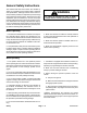
General Safety Instructions The ProPass 200 has been tested and certified by TORO for compliance with existing safety standards and specifications. Although hazard control and accident prevention partially are dependent upon the design and configuration of the machine, these factors are also dependent upon the awareness, concern and proper training of the personnel involved in the operation, transport, maintenance and storage of the machine.
1. The Operator’s Manual provides information regarding the operation, general maintenance and maintenance intervals for your ProPass machine. Refer to this publication for additional information when servicing the machine. 8. Before disconnecting any hydraulic component or performing any work on the hydraulic system, all pressure in system must be relieved. See Relieving Hydraulic System Pressure in the General Information section of Chapter 3 -- Hydraulic System. 2.
Safety and Instruction Decals Numerous safety and instruction decals are affixed to the ProPass 200. If any decal becomes illegible or damaged, install a new decal. Decal part numbers are listed in your Parts Catalog.
Chapter 2 Product Records and Maintenance Table of Contents 1 1 2 2 2 3 3 3 Product Records and Maintenance PRODUCT RECORDS . . . . . . . . . . . . . . . . . . . . . . . . . MAINTENANCE . . . . . . . . . . . . . . . . . . . . . . . . . . . . . . EQUIVALENTS AND CONVERSIONS . . . . . . . . . . . Decimal and Millimeter Equivalents . . . . . . . . . . . . U.S. to Metric Conversions . . . . . . . . . . . . . . . . . . . TORQUE SPECIFICATIONS . . . . . . . . . . . . . . . . . . . Fastener Identification . . .
Equivalents and Conversions 0.
Torque Specifications These Torque Specifications for the installation and tightening of fasteners shall apply to all fasteners which do not have a specific requirement identified in this Service Manual. The following factors shall be considered when applying torque: cleanliness of the fastener, use of a thread sealant (e.g. Loctite), degree of lubrication on the fastener, presence of a prevailing torque feature (e.g.
Standard Torque for Dry, Zinc Plated and Steel Fasteners (Inch Series) Thread Size # 6 -- 32 UNC Grade 1, 5 & 8 with Thin Height Nuts SAE Grade 1 Bolts, Screws, Studs & Sems with Regular Height Nuts (SAE J995 Grade 2 or Stronger Nuts) in--lb in--lb N--cm 10 + 2 13 + 2 147 + 23 # 6 -- 40 UNF # 8 -- 32 UNC 13 + 2 25 + 5 282 + 30 # 8 -- 36 UNF # 10 -- 24 UNC 18 + 2 30 + 5 339 + 56 # 10 -- 32 UNF SAE Grade 5 Bolts, Screws, Studs & Sems with Regular Height Nuts (SAE J995 Grade 2 or Stronger N
Standard Torque for Dry, Zinc Plated and Steel Fasteners (Metric Series) Class 8.8 Bolts, Screws and Studs with Regular Height Nuts (Class 8 or Stronger Nuts) Class 10.9 Bolts, Screws and Studs with Regular Height Nuts (Class 10 or Stronger Nuts) M5 X 0.8 57 + 6 in--lb 644 + 68 N--cm 78 + 8 in--lb 881 + 90 N--cm M6 X 1.0 96 + 10 in--lb 1085 + 113 N--cm 133 + 14 in--lb 1503 + 158 N--cm M8 X 1.25 19 + 2 ft--lb 26 + 3 N--m 28 + 3 ft--lb 38 + 4 N--m M10 X 1.
Other Torque Specifications SAE Grade 8 Steel Set Screws Wheel Bolts and Lug Nuts Recommended Torque Thread Size Thread Size Square Head Hex Socket 1/4 -- 20 UNC 140 + 20 in--lb 73 + 12 in--lb 5/16 -- 18 UNC 215 + 35 in--lb 145 + 20 in--lb 3/8 -- 16 UNC 35 + 10 ft--lb 18 + 3 ft--lb 1/2 -- 13 UNC 75 + 15 ft--lb 50 + 10 ft--lb Recommended Torque** 7/16 -- 20 UNF Grade 5 65 + 10 ft--lb 88 + 14 N--m 1/2 -- 20 UNF Grade 5 80 + 10 ft--lb 108 + 14 N--m M12 X 1.25 Class 8.
Chapter 3 Hydraulic System SPECIFICATIONS . . . . . . . . . . . . . . . . . . . . . . . . . . . . 2 GENERAL INFORMATION . . . . . . . . . . . . . . . . . . . . . 3 Operator’s Manual . . . . . . . . . . . . . . . . . . . . . . . . . . 3 ProPass Hydraulic Supply . . . . . . . . . . . . . . . . . . . . 3 Hydraulic Hose Kit (Tow Vehicle to ProPass) . . . . 3 Machine Hydraulic Control . . . . . . . . . . . . . . . . . . . 4 Rear Option . . . . . . . . . . . . . . . . . . . . . . . . . . . . . . . .
Specifications Item Description Tow Vehicle Hydraulic Supply Minimum Supply Maximum Supply 6 US Gal/Min (23 L/Min) @ 2000 PSI (138 Bar) 10 US Gal/Min (38 L/Min) @ 2800 PSI (190 Bar) Floor Motor Displacement (per revolution) Eaton fixed displacement geroler motor 22.7 in3 (371 cc) Twin Spinner Motors (Rear Option) Displacement (per revolution) Eaton fixed displacement geroler motor 1.8 in3 (29 cc) Conveyor Motor (Rear Option) Displacement (per revolution) Eaton fixed displacement geroler motor 1.
General Information Operator’s Manual The Operator’s Manual provides information regarding the operation, general maintenance and maintenance intervals for your ProPass machine. Refer to that publication for additional information when servicing the machine. ProPass Hydraulic Supply Hydraulic System Hydraulic supply for the ProPass machine is either provided by the tow vehicle or a hydraulic power pack.
Machine Hydraulic Control ProPass 200 machines use either standard hydraulic controls or electronic hydraulic controls to allow the operator to change machine settings. 2 Standard Hydraulic Controls 1 Machines with standard hydraulic controls include manual hydraulic controls on the front of the ProPass hopper to adjust hydraulic flow to the floor and rear option (twin spinner or conveyor) motors (Fig. 2).
Rear Option The ProPass includes the twin spinner that is used for topdressing (Fig. 5). The twin spinner uses two (2) hydraulic motors for operation. The cross conveyor and swivel is available as an option for delivery of material from the ProPass hopper (Fig. 6). The conveyor uses one (1) hydraulic motor for operation. The ProPass hydraulic system is used to operate either of these rear options.
Hydraulic Hoses Hydraulic hoses are subject to extreme conditions such as pressure differentials during operation and exposure to weather, sun, chemicals, very warm storage conditions or mishandling during operation and maintenance. These conditions can cause hose damage and deterioration. Some hoses are more susceptible to these conditions than others.
4. Thread the hose/tube swivel nut onto the fitting by hand. While holding the hose/tube with a wrench, use a torque wrench to tighten the swivel nut to the recommended installation torque shown in Figure 9. This tightening process will require the use of an offset wrench (e.g. crowfoot wrench). Use of an offset wrench will affect torque wrench calibration due to the effective length change of the torque wrench.
Hydraulic Hose and Tube Installation (JIC Flared Fittings) NOTE: ProPass machines with serial numbers below 310001000 use JIC flared fittings (Fig. 10). Use the following information when installing hydraulic hoses and tubes to JIC flared fittings. Size 4 (1/4 in. nominal hose or tubing) 6 (3/8 in.) 8 (1/2 in.) 10 (5/8 in.) 12 (3/4 in.) 16 (1 in.) 1. Make sure threads and sealing surfaces of the hose/ tube and the fitting are free of burrs, nicks, scratches or any foreign material. 2.
Hydraulic O--Ring Face Seal (ORFS) Fitting Installation (SAE Straight Thread O--Ring Fitting into Component Port) Non--Adjustable Fitting (Fig. 13) 5. If a torque wrench is not available, or if space at the port prevents use of a torque wrench, an alternate method of assembly is the Flats From Finger Tight (F.F.F.T.) method. 1. Make sure all threads and sealing surfaces of fitting and component port are free of burrs, nicks, scratches or any foreign material. 2.
Adjustable Fitting (Fig. 15) 1. Make sure all threads and sealing surfaces of fitting and component port are free of burrs, nicks, scratches or any foreign material. 2. As a preventative measure against leakage, it is recommended that the O--ring be replaced any time the connection is opened. 1 3. Lightly lubricate the O--ring with clean hydraulic oil. Fitting threads should be clean with no lubricant applied. 2 4. Turn back the lock nut as far as possible.
Hydraulic JIC Flared Fitting Installation (JIC Flared Fitting into Component Port) NOTE: ProPass machines with serial numbers below 310001000 use JIC flared fittings (Fig. 10). Use the following information when installing JIC flared fittings. When installing a JIC flared fitting into a component port, follow the same procedures as listed in Hydraulic O--Ring Face Seal (ORFS) Fitting Installation (SAE Straight Thread O--Ring Fitting into Component Port) found earlier in this section.
Hydraulic Schematics OPTION SOLENOID VALVE FLOOR SOLENOID VALVE CF FLOOR CONTROL VALVE IN EX OPTION CONTROL VALVE IN EX FLOOR MOTOR HYDRAULIC POWER PACK CF SPINNER MOTORS CONVEYOR MOTOR ProPass 200 Hydraulic Schematic Standard Hydraulic Controls All solenoids are shown as de--energized NOTE: The hydraulic schematic shown above includes the hydraulic power pack as the hydraulic supply source.
PLUG FA FB CV1 PLUG LA FLOOR MOTOR LB CV2 CV3 O T1 CV4 ORF4 (0.020) SP1 SV1 PV1 S2 S1 S2 S1 ORF3 (0.068) SPINNER MOTORS Hydraulic System EC1 ORF2 (0.020) ORF1 (0.040) CONTROL MANIFOLD P T CONVEYOR MOTOR M HYDRAULIC POWER PACK ProPass 200 Hydraulic Schematic Electronic Hydraulic Controls All solenoids are shown as de--energized NOTE: The hydraulic schematic shown above includes the hydraulic power pack as the hydraulic supply source.
Hydraulic Flow Diagrams: Standard Hydraulic Controls REAR OPTION CIRCUIT (TWIN SPINNER SHOWN) OPTION SOLENOID VALVE FLOOR SOLENOID VALVE CF FLOOR CONTROL VALVE IN EX OPTION CONTROL VALVE IN EX FLOOR MOTOR HYDRAULIC POWER PACK CF SPINNER MOTORS Option solenoid valve is energized. Excess and return flow will be routed to hydraulic reservoir.
Rear Option Circuit (Twin Spinner or Conveyor) Machines with standard hydraulic controls include manual hydraulic controls on the front of the ProPass hopper to adjust hydraulic flow to the floor and rear option (twin spinner or conveyor) motors (Fig. 19). A pendant electrical control allows the operator to energize the floor and rear option motors from the operator position of the tow vehicle.
Hydraulic Flow Diagrams: Electronic Hydraulic Controls REAR OPTION CIRCUITS (TWIN SPINNER OR CONVEYOR) PLUG FA FB CV1 PLUG LA LB CV2 CV3 SP1 FLOOR MOTOR O CV4 T1 ORF4 (0.020) SV1 PV1 S2 S1 S2 S1 ORF3 (0.068) SPINNER MOTORS EC1 ORF1 (0.040) ORF2 (0.020) CONTROL MANIFOLD P T CONVEYOR MOTOR M HYDRAULIC POWER PACK SP1 is not energized. PV1 is energized. Both EC1 and PV1 shift to allow flow to rear option motors. Excess and return flow will be routed to hydraulic reservoir.
Rear Option Circuits (Twin Spinner or Conveyor) Control manifold pressure compensator valve (EC1) is used to provide priority flow in the required amount to the floor motor while allowing excess flow to be used for operation of the rear option motors. If the floor circuit is not engaged, the pressure compensator valve directs all of the hydraulic flow toward the rear option motors and return to the hydraulic reservoir.
FLOOR CIRCUIT PLUG FA FB CV1 PLUG LA LB CV2 CV3 SP1 FLOOR MOTOR O CV4 T1 ORF4 (0.020) SV1 PV1 S2 S1 S2 S1 ORF3 (0.068) SPINNER MOTORS EC1 ORF2 (0.020) ORF1 (0.040) CONTROL MANIFOLD P T CONVEYOR MOTOR M HYDRAULIC POWER PACK SP1 and PV1 are both energized. Both EC1 and PV1 shift to allow proportional flow to rear option and floor motors. Excess and return flow will be directed to hydraulic reservoir.
Floor Circuit Control manifold pressure compensator valve (EC1) is used to provide priority flow in the required amount to the floor motor while allowing excess flow to be used for operation of the rear option motors. If the floor circuit is not engaged, the pressure compensator valve directs all of the hydraulic flow toward the rear option motors and return to the hydraulic reservoir. Control manifold proportional flow valve (PV1) is a priority--type flow regulator with pressure compensated bypass flow.
Special Tools Order the following special tools from your Toro Distributor. Hydraulic Pressure Test Kit Use to take various pressure readings for diagnostic tests. Quick disconnect fittings provided attach directly to mating fittings on machine test ports without tools. A high pressure hose is provided for remote readings. Contains one each: 1000 PSI (70 Bar), 5000 PSI (350 Bar) and 10000 PSI (700 Bar) gauges.
Hydraulic Test Fitting Kit This kit includes a variety of O--ring Face Seal fittings to enable you to connect test gauges into the system. The kit includes: tee’s, unions, reducers, plugs, caps and male test fittings. Toro Part Number: TOR4079 Figure 24 O--ring Kit Hydraulic System This kit includes O--rings in a variety of sizes for face seal and port seal hydraulic connections. It is recommended that O--rings be replaced whenever a hydraulic connection is loosened.
Troubleshooting For effective troubleshooting and repairs, there must be a good understanding of the hydraulic circuits and components used on this machine (see Hydraulic Schematics in this chapter). Problem Possible Causes No ProPass functions operate. Hydraulic lines are not connected to tow vehicle (machines that use hydraulic flow from tow vehicle). Hydraulic lines to tow vehicle are not connected correctly (machines that use hydraulic flow from tow vehicle). Hydraulic reservoir level is low.
Problem Possible Causes Floor does not function (machines with standard hydraulics). Floor control valve setting is not adjusted properly. Floor solenoid valve is faulty. An electrical problem exists (see Chapter 4 -- Electrical System). Hydraulic floor motor is faulty. Floor does not function (machines with electronic hydraulics). NOTE: Check wireless remote LCD display and base unit LED’s for help in troubleshooting. Wireless remote settings are incorrect.
Testing The most effective method for isolating problems in the hydraulic system is by using hydraulic test equipment such as pressure gauges and flow meters in the circuits during various operational checks (see the Special Tools section in this chapter). IMPORTANT: All obvious areas such as oil supply, filter, binding linkages, loose fasteners or improper adjustments must be checked before assuming that a hydraulic component is the source of the problem.
Hydraulic System This page is intentionally blank.
Service and Repairs General Precautions for Removing and Installing Hydraulic System Components Before Repair or Replacement of Hydraulic Components After Repair or Replacement of Hydraulic Components 1. Before removing any components from the hydraulic system, position ProPass machine on a level surface. Engage tow vehicle parking brake, stop engine and remove key from the ignition switch. If ProPass is equipped with wireless controller, power off wireless controller. 1.
Check Hydraulic Lines and Hoses IMPORTANT: Check hydraulic lines and hoses daily for leaks, kinked lines, loose mounting supports, wear, loose fittings or deterioration. Make all necessary repairs before operating the machine. WARNING Hydraulic System Keep body and hands away from pin hole leaks or nozzles that eject hydraulic fluid under high pressure. Use paper or cardboard, not hands, to search for leaks.
Hydraulic Control (Machines with Standard Hydraulic Controls) 5 RIGHT FRONT 6 2 8 7 6 21 8 16 4 1 17 15 5 3 23 22 10 1 18 25 13 9 10 20 22 12 16 10 21 22 14 1 11 10 24 26 27 19 16 Figure 26 1. 2. 3. 4. 5. 6. 7. 8. 9. Hydraulic tee fitting (3 used) Panel Floor control valve Rear option control valve Hydraulic hose Hydraulic hose Hydraulic hose Hydraulic hose Hydraulic cap Hydraulic System 10. 11. 12. 13. 14. 15. 16. 17. 18.
Disassembly (Fig. 26) 1. Position machine on a level surface. If ProPass is attached to tow vehicle, apply tow vehicle parking brake, stop engine and remove key from the ignition switch. Chock wheels to prevent ProPass machine from moving. 2 3 3 2. Remove hydraulic guard from machine to allow access to hydraulic controls (Fig. 27). CAUTION 5 4 1 Figure 27 1. Hydraulic guard 2. Screw (2 used) 3. Flange nut (4 used) 4. Cap screw (2 used) 5.
Control Valve Service (Machines with Standard Hydraulic Controls) ProPass machines with standard hydraulic controls use two (2) control valves for adjusting the speed of the floor and rear option (twin spinner or conveyor) motors. These control valves are located on the front of the hopper (Fig. 29). 2 1 NOTE: See Hydraulic Control (Machines with Standard Hydraulic Controls) in this section for information on removing the control valve from the machine. Disassembly (Fig.
Solenoid Valve Assembly (Machines with Standard Hydraulic Controls) Two (2) identical solenoid valve assemblies are used on machines with standard hydraulic controls. When energized, these solenoid valves allow hydraulic flow to engage the floor and rear option (twin spinner or conveyor) motors. NOTE: See Hydraulic Control (Machines with Standard Hydraulic Controls) in this section for information on removing the solenoid valve assembly from the machine. CAUTION 2 1 Figure 31 1.
Hydraulic Control (Machines with Electronic Hydraulic Controls) 10 17 5 RIGHT FRONT 19 1 15 5 16 17 2 6 18 13 7 1 18 8 3 12 11 17 14 21 20 17 12 9 2 3 6 12 17 7 12 12 17 4 7 Figure 33 1. 2. 3. 4. 5. 6. 7. Hydraulic hose Hydraulic hose Hydraulic hose Hydraulic control manifold Hydraulic hose Straight hydraulic fitting (2 used) Straight hydraulic fitting (4 used) Hydraulic System 8. 9. 10. 11. 12. 13. 14.
Removal (Fig. 33) 1. Position machine on a level surface. If ProPass is attached to tow vehicle, apply tow vehicle parking brake, stop engine and remove key from the ignition switch. Chock wheels to prevent ProPass machine from moving. 2. Disconnect emergency stop button connector from machine wire harness. Remove control panel guard from front of ProPass to allow access to control manifold. CAUTION 3. Remove caps and plugs from disconnected hydraulic lines and manifold fittings. 4.
Hydraulic Control Manifold (Machines with Electronic Hydraulic Controls) 10 8 8 25 ft--lb (34 N--m) 60 in--lb (6.7 N--m) 9 9 7 8 8 4 6 25 ft--lb (34 N--m) 35 ft--lb (47 N--m) 3 35 ft--lb (47 N--m) 5 25 ft--lb (34 N--m) 2 UP 25 ft--lb (34 N--m) 1 13 20 ft--lb (27 N--m) 11 11 UP 12 13 16 12 14 16 15 12 12 11 12 to 14 ft--lb (16 to 18 N--m) 12 20 ft--lb (27 N--m) 11 17 20 to 26 ft--lb (27 to 35 N--m) Figure 36 1. 2. 3. 4. 5. 6.
NOTE: The hydraulic manifold shown in Figure 36 uses several zero leak plugs. These plugs have a tapered sealing surface on the plug head that is designed to resist vibration induced plug loosening. The zero leak plugs also have an O--ring to provide a secondary seal. If zero leak plug removal is necessary, lightly rap the plug head using a punch and hammer before using an allen wrench to remove the plug: the impact will allow plug removal with less chance of damage to the socket head of the plug.
Check Valve Service 3 The ProPass control manifold includes four (4) check valves used for circuit control. Check valve location is identified in Figure 37. Remove check valves from manifold for cleaning or replacement. Replace seal kit on check valves if removed from manifold. Torque check valves from 12 to 14 ft--lb (16 to 18 N--m) when installing them into manifold. 1 2 4 NOTE: Check valves CV3 and CV4 are not used in the ProPass 200 hydraulic system.
Hydraulic System This page is intentionally blank.
Floor Motor Loctite #242 9 11 15 4 12 15 17 2 7 18 6 15 Loctite #242 Antiseize Lubricant 10 8 1 7 5 3 14 13 15 Loctite #242 16 Antiseize Lubricant FRONT Direction Of Rotation RIGHT Figure 39 1. 2. 3. 4. 5. 6. Drive chain Hydraulic floor motor Sprocket Sprocket Idler sprocket Cap screw 7. 8. 9. 10. 11. 12. Flat washer (2 used) Lock nut Cap screw (2 used) Lock nut (2 used) Cap screw Flat washer Removal (Fig. 39) 1. Position machine on a level surface.
4. Locate and remove master link (item 16) from drive chain. Note direction of master link clip for assembly purposes. Remove drive chain. CAUTION 4. Position woodruff key to slot in floor motor shaft and then slide sprocket (item 4) onto shaft. 5. Install cap screw (item 11) and flat washer (item 12) into end of floor motor shaft. 6. Slide sprocket to end of motor shaft so that it contacts flat washer. 5. Relieve hydraulic system pressure. 6. Clean floor motor and all hydraulic connections at motor.
Floor Motor Service 17 9 Loctite #601 250 in--lb (28 N--m) 8 7 6 2 5 4 16 1 15 11 3 14 11 300 in--lb (34 N--m) 13 12 11 10 Figure 41 1. 2. 3. 4. 5. 6. Cap screw (4 used) Mounting flange Exclusion seal Back--up ring Pressure seal Seal 7. 8. 9. 10. 11. 12. Bearing race Thrust bearing Output shaft Housing Seal (3 used) Spacer plate 13. 14. 15. 16. 17.
Hydraulic System This page is intentionally blank.
Twin Spinner Motors 32 22 23 31 24 33 21 20 Antiseize Lubricant 11 30 13 17 2 5 9 14 13 19 28 4 9 9 12 1 14 26 27 3 5 7 25 27 29 5 13 Antiseize Lubricant 6 18 9 8 5 13 RIGHT Loctite #242 17 15 16 10 FRONT Figure 42 1. 2. 3. 4. 5. 6. 7. 8. 9. 10. 11.
Removal (Fig. 42) Installation (Fig. 42) 1. Position machine on a level surface. If ProPass is attached to tow vehicle, apply tow vehicle parking brake, stop engine and remove key from the ignition switch. Chock wheels to prevent ProPass machine from moving. 1. If removed, install hydraulic fittings with new O--rings into the spinner motor ports (see Hydraulic Fitting Installation in the General Information section of this chapter). CAUTION 2.
Conveyor Motor 11 Loctite #242 8 12 1 13 14 15 16 7 2 5 4 5 10 3 20 6 18 9 17 19 6 21 Antiseize Lubricant 7 Figure 43 1. 2. 3. 4. 5. 6. 7. Cap screw (2 used per bearing) Flange nut (2 used per bearing) Adjuster plate (2 used) Flange head screw (2 used) Jam nut (4 used) Flange bearing (3 used) Bearing guard (3 used) Hydraulic System 8. 9. 10. 11. 12. 13. 14.
1. Position machine on a level surface. If ProPass is attached to tow vehicle, apply tow vehicle parking brake, stop engine and remove key from the ignition switch. Chock wheels to prevent ProPass machine from moving. 2. Loosen conveyor belt tension: A. Loosen cap screws (item 1) and flange nuts (item 2) that secure adjuster plates (item 3) and flange bearings (item 6) to conveyor cover. B.
Rear Option Motor Service Loctite #277 250 in--lb (28 N--m) 8 9 10 11 12 13 15 14 16 17 1 2 3 4 3 5 235 to 250 in--lb (27 to 28 N--m) 6 3 7 Figure 44 1. 2. 3. 4. 5. 6. Cap screw (7 used) End cap Seal (3 used) Geroler assembly Spacer plate Drive 7. 8. 9. 10. 11. 12. Housing Output shaft Woodruff key Thrust bearing Bearing race Seal The hydraulic motor used for the ProPass rear option (twin spinner or conveyor) is the same basic motor regardless of which option exists.
Chapter 4 Electrical System Table of Contents ProPass 200 Page 4 -- 1 Electrical System GENERAL INFORMATION . . . . . . . . . . . . . . . . . . . . . 3 Operator’s Manual . . . . . . . . . . . . . . . . . . . . . . . . . . 3 Machine Hydraulic Control . . . . . . . . . . . . . . . . . . . 3 ELECTRICAL SCHEMATICS . . . . . . . . . . . . . . . . . . . 4 ProPass with Standard Hydraulic Controls . . . . . . 4 ProPass with Electronic Hydraulic Controls . . . . . 6 WIRE HARNESS DRAWINGS . . . . . . . . . . . .
This page is intentionally blank.
General Information Operator’s Manual The Operator’s Manual provides information regarding the operation, general maintenance and maintenance intervals for your ProPass machine. Refer to the Operator’s Manual for additional information when servicing the machine. Machine Hydraulic Control ProPass 200 machines use either standard hydraulic controls or electronic hydraulic controls to allow the operator to change machine settings.
Electrical Schematics Machines with Standard Hydraulic Controls PENDANT ASSEMBLY FLOOR SOLENOID VALVE FLOOR SWITCH GREEN WHITE BLACK BLACK REAR OPTION SWITCH REAR OPTION SOLENOID VALVE 15A FUSE WHITE 15A FUSE BLACK WHITE NOTE: Electrical power is provided by either the tow vehicle or the hydraulic power pack.
CHASSIS GROUND P03 J01 1 B BK BK FLOOR SOLENOID L14 P03 A REMOTE CONNECTION P05 GN BK BK GN WH L13 SP01 P04 B BK BK BK P04 A BN BN P05 1 1 2 2 3 3 4 4 GN WH SW02 BN BN F05 P01 A WH WH BK P01 -+ J01 J02 BK WH BK WH BATTERY CONNECTIONS B 10A F01 A J01 WH POWER INTERCONNECTS P02 15A J02 ATTACHMENT SOLENOID SWITCH 15A FUSE B WH GN ATTACHMENT SOLENOID WH FLOOR SOLENOID SWITCH SW01 J02 J01 WH WH BRAKE FUSE P02 2 2 1 1 WH BK P01 1 1 2 2 3
Machines with Electronic Hydraulic Controls BASE UNIT E--STOP BUTTON Electrical System FLOOR SP1 (LOWER COIL) REAR OPTION PV1 WIRELESS REMOTE CONTROL MANIFOLD POWER LEAD HARNESS INCLUDES 15 AMP IN--LINE FUSE TOW VEHICLE POWER LEAD HARNESS NOTE: Electrical power is provided by either the tow vehicle or the hydraulic power pack.
122--0271 Rev A Machines with Electronic Hydraulic Controls (Machine serial numbers below 401380000) Figure 6 ProPass 200 Page 4 -- 7 Electrical System
Page 4 -- 8 YE UP SW16 3 COM 2 COM DOWN 1 COM P16 PK J02 J01 WH BK BATTERY CONNECTIONS A NO 6 B NC 8 B NO 5 C NC 7 -+ P16 C NO 4 WH F01 BRAKE FUSE 10A SP11 A P02 MINI FUSE HOLDER TBD B PK SP07 B BK/WH BK/WH WH PK PK P06 SP06 SP04 A RD/WH RD/WH RD/WH RD/WH SP05 BK/WH BK/WH BK/WH C R01 4 3 2 1 P04 WH BK YE BK CAN1 -- CAN1 + CAN2 -- CAN2 + 4 2 2 3 1 1 4 P01 P01 3 1 2 P02 1 2 P10 CAN DIAG P05 C B CAP A WH BK BK WH PK OG OG PK G
122--1502 Rev A Machines with Electronic Hydraulic Controls (Machine serial numbers above 403500001) Figure 8 ProPass 200 Page 4 -- 9 Electrical System
Wire Harness Drawings P01 P01 BLACK J01 WHITE WHITE J02 P02 PROPASS 200 POWER LEAD WIRE HARNESS (FROM TOW VEHICLE) Figure 9 P01 BLACK YELLOW J02 RED P02 J01 PROPASS 200 POWER LEAD WIRE HARNESS (FROM HYDRAULIC POWER PACK) Figure 10 Electrical System Page 4 -- 10 ProPass 200
BLACK WHITE PROPASS 200 INTERMEDIATE POWER WIRE HARNESS Electrical System Figure 11 ProPass 200 Page 4 -- 11 Electrical System
Electrical System BLACK BLACK BLACK BLACK WHITE GREEN WHITE BROWN PROPASS 200 MAIN VALVE WIRE HARNESS STANDARD HYDRAULIC CONTROLS Figure 12 Electrical System Page 4 -- 12 ProPass 200
J02 P01 J03 J04 J01 GREEN J01 OPTION SWITCH WHITE P01 J02 WHITE J03 FLOOR SWITCH BLACK J04 PROPASS 200 PENDANT WIRE HARNESS STANDARD HYDRAULIC CONTROLS Figure 13 ProPass 200 Page 4 -- 13 Electrical System
BASE UNIT YELLOW PINK BLACK BASE UNIT BLACK BLACK BLACK BLUE GREEN PROPASS 200 BULKHEAD WIRE HARNESS ELECTRONIC HYDRAULIC CONTROLS Figure 14 Electrical System Page 4 -- 14 ProPass 200
CV 122--0336 Rev B Machines with Electronic Hydraulic Controls (Machine serial numbers below 401380000) (Sheet 1 of 2) Figure 15 ProPass 200 Page 4 -- 15 Electrical System
122--0336 Rev B Machines with Electronic Hydraulic Controls (Machine serial numbers below 401380000) (Sheet 2 of 2) Figure 16 Electrical System Page 4 -- 16 ProPass 200
CV 122--1148 Rev A Machines with Electronic Hydraulic Controls (Machine serial numbers 401380001 to 403500000) (Sheet 1 of 2) Figure 17 ProPass 200 Page 4 -- 17 Electrical System
122--1148 Rev A Machines with Electronic Hydraulic Controls (Machine serial numbers 401380001 to 403500000) (Sheet 2 of 2) Figure 18 Electrical System Page 4 -- 18 ProPass 200
CV 122--1501 Rev A Machines with Electronic Hydraulic Controls (Machine serial numbers above 403500001) (Sheet 1 of 2) Figure 19 ProPass 200 Page 4 -- 19 Electrical System
122--1501 Rev A Machines with Electronic Hydraulic Controls (Machine serial numbers above 403500001) (Sheet 2 of 2) Figure 20 Electrical System Page 4 -- 20 ProPass 200
Special Tools Order special tools from your Toro distributor. Some tools may also be available from a local supplier. Multimeter The multimeter can test electrical components and circuits for current (amps), resistance (ohms) or voltage. Obtain this tool locally. NOTE: Toro recommends the use of a DIGITAL Volt-Ohm--Amp multimeter when testing electrical circuits.
Battery Terminal Protector Aerosol spray that should be used on battery terminals to reduce corrosion problems. Apply battery terminal protector after the battery cable has been secured to the battery terminal. Toro Part Number: 107--0392 Figure 24 Battery Hydrometer Electrical System Use the battery hydrometer when measuring specific gravity of battery electrolyte. Obtain this tool locally.
Troubleshooting For effective troubleshooting and repairs, there must be a good understanding of the electrical circuits and components used on this machine (see Electrical Schematics in this chapter). CAUTION Remove all jewelry, especially rings and watches, before doing any electrical troubleshooting or testing. Disconnect the battery cables unless the test requires battery voltage. If the machine has any interlock switches by--passed, reconnect the switches for proper safety and troubleshooting.
Problem Possible Causes Rear option does not function (machines with Wireless remote has not been turned ON. electronic hydraulics). NOTE: Start button on remote must be pushed twice to Wireless remote has timed out due to thirty (30) minutes of inactivity. activate rear option. Also, check wireless remote LCD display and base unit LED’s for help in troubleshooting. Wireless remote settings are incorrect. Proportional flow valve coil (PV1) or circuit wiring is faulty.
Component Testing For accurate resistance and/or continuity checks, electrically disconnect the component being tested from the circuit (e.g. unplug the wire harness connector from component before checking continuity on the component terminals). CAUTION When testing electrical components for continuity with a multimeter (ohms setting), make sure that power to the circuit has been disconnected.
Pendant Assembly (Machines with Standard Hydraulic Controls) The pendant assembly allows the machine operator to engage the rear option (twin spinner or conveyor) and the floor from the tow vehicle operator’s position. The pendant assembly includes two (2) switches, the junction box and the wire harness (Fig. 27). 2 4 3 Figure 27 1. Rear option switch 2. Floor switch 3. Junction box 4.
Wireless Remote (Machines with Electronic Hydraulic Controls) The wireless remote is a solid state electrical device that sends radio frequency (RF) signal inputs to the machine wireless remote base unit for control of machine electrical operation. The wireless remote has sufficient range to send an RF signal to the remote base unit from the tow vehicle operator position. LCD Display The wireless remote LCD display can be used to identify activity between the remote and the base unit.
Meaning ASSOC PENDING Association between remote and base unit has yet to be made. ASSOC ACTIVE Association attempt between remote and base unit is in progress. CLR CHAN SCAN A scan to find a clear channel is in progress. POW UP BUNIT The base unit is being powered up. ASSOC SUCCESS Association between remote and base unit has been made. ALL STORE Store all currently set values into memory. OPTION STORE Store the current rear option settings into memory.
Wireless Remote Base Unit (Machines with Electronic Hydraulic Controls) The base unit is a solid state electrical device that receives signal inputs from the wireless remote and uses those inputs to control machine electrical operation. The base unit is attached to the front hopper wall next to the hydraulic control manifold (Fig. 32). 2 4 Inputs from the wireless remote are monitored by the base unit.
Hydraulic Solenoid Valve Coils The ProPass hydraulic system uses several hydraulic solenoid valve coils for system control. When the solenoid coils are energized, hydraulic valve shift occurs to control hydraulic flow. Two (2) identical solenoid valve assemblies are used on machines with standard hydraulic controls (Fig. 34). The solenoid valve coils used on these assemblies are identical. Machines with electronic hydraulic controls use two (2) different solenoid valve coils (Fig. 35).
Chapter 5 Chassis Table of Contents Chassis GENERAL INFORMATION . . . . . . . . . . . . . . . . . . . . . 3 Operator’s Manual . . . . . . . . . . . . . . . . . . . . . . . . . . 3 Parts Catalog . . . . . . . . . . . . . . . . . . . . . . . . . . . . . . . 3 SERVICE AND REPAIRS . . . . . . . . . . . . . . . . . . . . . . 4 Bed Guards . . . . . . . . . . . . . . . . . . . . . . . . . . . . . . . . 4 Floor Motor Drive . . . . . . . . . . . . . . . . . . . . . . . . . . . 6 Drive Roller Bearings . . . . . .
This page is intentionally blank.
General Information Operator’s Manual The Operator’s Manual provides information regarding the operation, general maintenance and maintenance intervals for your ProPass machine. Refer to this publication for additional information when servicing the machine. Parts Catalog Chassis The Parts Catalog can be used to provide general disassembly and assembly information for the chassis on your ProPass machine. Refer to this publication for additional information when servicing the machine.
Service and Repairs Bed Guards 12 11 10 8 13 9 RIGHT 14 2 FRONT 13 3 14 13 6 13 13 14 5 15 14 13 16 1 7 13 15 16 4 Figure 1 1. 2. 3. 4. 5. 6. Bottom guard RH drive guard Guard cap LH idler guard RH idler guard LH drive guard Chassis 7. 8. 9. 10. 11. Front rinse guard Shoulder nut (2 used) Lanyard (2 used) Flat washer (2 used) Rivet (2 used) Page 5 -- 4 12. 13. 14. 15. 16.
Disassembly (Fig. 1) MACHINES WITH ELECTRONIC HYDRAULIC CONTROLS 1. Position machine on a level surface. If ProPass is attached to tow vehicle, apply tow vehicle parking brake, stop engine and remove key from the ignition switch. Chock wheels to prevent ProPass machine from moving. 1 2. If front rinse guard is to be removed from machine with electronic controls (Fig. 2): 3 4 5 6 A. Disconnect E--stop button from machine wire harness. B. Remove fasteners that secure control panel guard to machine.
Floor Motor Drive Loctite #242 9 11 15 12 4 15 17 2 7 18 6 15 Loctite #242 Antiseize Lubricant 10 8 1 7 5 14 13 3 15 Loctite #242 16 Antiseize Lubricant FRONT Direction Of Rotation RIGHT Figure 3 1. 2. 3. 4. 5. 6. Drive chain Hydraulic floor motor Sprocket Sprocket Idler sprocket Cap screw Chassis 7. 8. 9. 10. 11. 12. Flat washer (2 used) Lock nut Cap screw (2 used) Lock nut (2 used) Cap screw Flat washer Page 5 -- 6 13. 14. 15. 16. 17. 18.
Disassembly (Fig. 3) 1. Position machine on a level surface. If ProPass is attached to tow vehicle, apply tow vehicle parking brake, stop engine and remove key from the ignition switch. Chock wheels to prevent ProPass machine from moving. 2. Remove guard cap and RH drive guard from frame to allow access to floor drive components (Fig. 4). 3. Loosen cap screw and lock nut that secure idler sprocket (item 5) to frame. Move idler sprocket to remove tension from drive chain. 4 8 5 7 2 6 9 3 2 1 2 4.
Drive Roller Bearings 1 3 Loctite #242 Loctite #242 6 2 5 4 RIGHT 3 1 FRONT 4 7 2 8 Figure 6 1. Set screw 2. Locking collar 3. Lock nut (4 used per bearing) 4. Bearing assembly 5. Drive roller shaft 6. Cap screw (4 used per bearing) Use this procedure for service of the drive roller bearings at the rear of the machine. Disassembly (Fig. 6) 1. Position machine on a level surface.
Assembly (Fig. 6) 4 1. Slide bearing onto cap screws that are inserted into frame. Secure bearing to frame with four (4) lock nuts (item 3). 1 2. Install and tighten locking collar to drive roller shaft (Fig. 8): A. Slide locking collar to bearing assembly and drive roller shaft. B. Using blind hole in locking collar as an impact point, lock collar by striking it with a punch in the direction of drive roller shaft rotation. C. Apply Loctite #242 (or equivalent) to threads of set screw.
Floor Conveyor Belt 3 RIGHT FRONT 4 6 7 8 2 9 9 10 1 12 11 5 Figure 10 1. 2. 3. 4. LH conveyor frame assembly Conveyor bed assembly RH conveyor frame assembly Floor conveyor belt 5. 6. 7. 8. Idler roller Drive roller Scraper assembly Cap screw (4 used) To remove and replace the floor conveyor belt, removal of the left side conveyor frame is recommended. This procedure allows the hydraulic motor and drive chain components to remain in place on the right side conveyor frame. Removal (Fig. 10) 1.
7. Remove fasteners (four (4) cap screws, washers and lock nuts) that secure scraper assembly (item 7) to conveyor frame. Remove scraper assembly. B. Inspect rubber skirts that seal the hopper and conveyor belt. If skirts are worn or damaged, replace them before installing hopper assembly. 8. On left side of machine, loosen bearing locking collar on both idler and drive roller shafts (see Drive Roller Bearings and Idler Roller Bearings in this section). C.
Idler and Drive Rollers 3 RIGHT FRONT 4 6 7 8 2 9 9 10 1 12 11 5 Figure 12 1. 2. 3. 4. LH conveyor frame assembly Conveyor bed assembly RH conveyor frame assembly Floor conveyor belt 5. 6. 7. 8. Idler roller Drive roller Scraper assembly Cap screw (4 used) 9. 10. 11. 12. Flat washer (8 used) Lock nut (4 used) Flange head screw (10 used) Flange nut (10 used) To remove and replace the idler and drive rollers, removal of the left side conveyor frame and the floor conveyor belt is necessary.
Removal (Fig. 12) Installation (Fig. 12) 1. Position machine on a level surface. If ProPass is attached to tow vehicle, apply tow vehicle parking brake, stop engine and remove key from the ignition switch. Chock wheels to prevent ProPass machine from moving. IMPORTANT: During roller installation, do not lock bearing collars on idler and roller shafts until after both sides of conveyor frame are assembled and rollers are centered in the frame. 2.
Idler Roller Take Up Bearings 3 RIGHT FRONT 4 6 7 8 2 9 9 10 1 12 11 5 13 15 14 15 19 18 16 14 Loctite #242 14 17 Figure 13 1. 2. 3. 4. 5. 6. 7. LH conveyor frame assembly Conveyor bed assembly RH conveyor frame assembly Floor conveyor belt Idler roller Drive roller Scraper assembly 8. 9. 10. 11. 12. 13. Cap screw (4 used) Flat washer (8 used) Lock nut (4 used) Flange head screw (10 used) Flange nut (10 used) Tensioner rod 14. 15. 16. 17. 18. 19.
Disassembly (Fig. 13) 4 1. Position machine on a level surface. If ProPass is attached to tow vehicle, apply tow vehicle parking brake, stop engine and remove key from the ignition switch. Chock wheels to prevent ProPass machine from moving. 1 2. Remove left side conveyor frame and the floor conveyor belt (see Floor Conveyor Belt in this section). 3. If right side idler roller take up bearing is to removed, remove idler roller from right side conveyor frame (see Idler and Drive Rollers in this section).
Wheel Assemblies (Tow Chassis) 19 RIGHT FRONT 1 94 to 116 ft--lb (128 to 157 N--m) 21 18 240 to 292 ft--lb (322 to 396 N--m) 25 14 15 135 to 165 ft--lb (183 to 223 N--m) 70 to 90 ft--lb (95 to 122 N--m) 5 17 8 27 24 23 10 9 16 20 7 26 13 28 22 2 29 6 4 3 12 11 Figure 15 1. 2. 3. 4. 5. 6. 7. 8. 9. 10.
Wheel Removal (Fig. 15) Wheel Installation (Fig. 15) 1. Position ProPass on a level surface attached to towing vehicle. Apply vehicle parking brake, stop engine and remove key from the ignition switch. Chock ProPass wheels to prevent machine from moving. 1. Position wheel to wheel hub. 2. Secure wheel to wheel hub with five (5) lug nuts. WARNING 2. Jack or hoist ProPass from ground and support machine with appropriate jack stands. 3.
Wheel Bearing Service (Tow Chassis) 1 4 See Text for Tightening Procedure 5 10 5 3 8 9 11 3 2 7 6 Figure 16 1. 2. 3. 4. Walking beam axle Hub (2 used per axle) Bearing cone (2 used per hub) Seal 5. 6. 7. 8. Bearing cup (2 used per hub) Dust cap Spindle washer Spindle nut 9. Nut retainer 10. Cotter pin 11. Wheel stud (5 used per hub) NOTE: The outer hub and wheel bearings can be removed with the walking beam attached to the ProPass machine.
5. Adjust wheel bearings as follows: Installation (Fig. 16) 1. Clean all parts thoroughly before reassembly. 2. Assemble wheel hub onto the same spindle from which it was removed: A. If bearing cups were removed from the wheel hub, press inner and outer cups into the hub until they seat against the hub shoulder. B. If wheel studs were removed from hub, press new studs into hub. Make sure that head of stud is fully to hub surface. C. Pack both bearing cones with grease.
Walking Beam Assembly (Tow Chassis) 19 RIGHT FRONT 1 94 to 116 ft--lb (128 to 157 N--m) 21 18 240 to 292 ft--lb (322 to 396 N--m) 25 14 15 135 to 165 ft--lb (183 to 223 N--m) 70 to 90 ft--lb (95 to 122 N--m) 5 17 8 27 24 23 10 9 20 13 28 22 16 7 26 2 29 6 4 3 12 11 Figure 17 1. 2. 3. 4. 5. 6. 7. 8. 9. 10.
Removal (Fig. 17) Installation (Fig. 17) 1. Position ProPass on a level surface attached to towing vehicle. Apply vehicle parking brake, stop engine and remove key from the ignition switch. Chock ProPass wheels to prevent machine from moving. 1. Slide bearings onto walking beam pivots. Position walking beam assembly under machine. Make sure that grease fittings in bearings are orientated toward the ground. 2. Jack or hoist ProPass from ground and support machine with appropriate jack stands. 2.
This page is intentionally blank.
Chapter 6 Hydraulic Power Pack Table of Contents Hydraulic Power Pack POWER PACK ENGINE SPECIFICATIONS . . . . . . 2 POWER PACK HYDRAULIC SPECIFICATIONS . . 3 GENERAL INFORMATION . . . . . . . . . . . . . . . . . . . . . 4 Engine Owner’s Manual . . . . . . . . . . . . . . . . . . . . . . 4 Installation Instructions . . . . . . . . . . . . . . . . . . . . . . 4 Parts Catalog . . . . . . . . . . . . . . . . . . . . . . . . . . . . . . . 4 Hydraulic Schematics . . . . . . . . . . . . . . . . . . . . . . . .
Power Pack Engine Specifications Item Description Make / Designation Honda Model GX340 4--Cycle, OHV, Gasoline Engine Bore 3.465” (88 mm) Stroke 2.520” (64 mm) 23.7 in3 (389 cc) Total Displacement Direction of Rotation Counterclockwise (viewed from PTO end) Fuel Regular Unleaded Gasoline with less than 10% Ethanol Fuel Capacity 6.4 U.S. Quarts (6.
Power Pack Hydraulic Specifications Item Description Gear Pump Eaton gear pump (Model 26001) 0.40 in3 (6.6 cc) Displacement (per revolution) Circuit Relief Pressure 2000 PSI (138 bar) Hydraulic Tank Capacity 8.7 U.S. Gallons (32.
General Information This Chapter gives information about specifications and repair of the engine and hydraulic components used in the ProPass Hydraulic Power Pack assembly. General maintenance procedures are described in your Traction Unit Operator’s Manual. Information on engine troubleshooting, testing, disassembly and assembly is identified in the Honda Workshop Manual that is available from Honda. Most engine repairs and adjustments require tools which are com- monly available in many service shops.
Electrical System Quick Checks Battery Test (Open Circuit Test) Use a multimeter to measure the voltage between the battery terminals. Voltage Measured Battery Charge Level 12.68 V (or higher) Fully charged (100%) Set multimeter to the DC volts setting. The battery should be at a temperature of 60o to 100oF (16o to 38oC). The ignition key should be off and all accessories turned off.
Adjustments Adjust Manifold Relief Valve The hydraulic relief valve manifold includes an adjustable relief valve for system relief (Fig. 1). If adjustment to this valve is necessary, follow the following procedure. 3 NOTE: Do not remove relief valve from the hydraulic manifold for adjustment. WARNING 1 Never adjust the relief valve with the hydraulic system pressurized. Hydraulic oil may spray out of the valve with the cap off. Personal injury may result.
Hydraulic Power Pack This page is intentionally blank.
Hydraulic Testing The most effective method for isolating problems in the hydraulic system is by using hydraulic test equipment such as pressure gauges and flow meters in the circuits during various operational checks. Information regarding special tools for hydraulic testing is in the Special Tools section of Chapter 3 -- Hydraulic System.
11. If gear pump flow is less than 5.2 GPM (19.7 LPM), check system relief valve for possible leakage as follows: E. When relief valve pressure has been determined, open control valve on tester, move throttle to low idle speed and shut off engine. Record relief valve pressure test results. A. Leave hydraulic tester (pressure and flow) installed as listed above. Make sure flow control valve on tester is fully open. F.
Hydraulic Power Pack Gear Pump Flow (Using Tester with Flowmeter and Pressure Gauge) The power pack gear pump flow test listed below should be performed after first determining that the system relief valve is operating correctly (see Hydraulic Power Pack Gear Pump Flow and System Relief Pressure Tests in this section). The following procedure is used to identify the gear pump flow directly from the pump outlet. 1.
Hydraulic Power Pack This page is intentionally blank.
Service and Repairs Engine RIGHT FRONT 13 6 16 2 22 18 15 1 14 3 10 22 12 11 18 5 4 7 20 9 18 8 21 18 19 18 GROUND CABLE CONNECTION 17 Figure 5 1. 2. 3. 4. 5. 6. 7. 8. Jaw coupling (engine) Spider coupling Jaw coupling (gear pump) Square key Engine Flange adapter Engine mount plate Mount bracket (4 used) 9. 10. 11. 12. 13. 14. 15. Flange nut (2 used) Cap screw (2 used) R--clamp (2 used) Engine wire harness Generator bracket Lock nut (2 used) Cap screw (2 used) Engine Removal (Fig.
CAUTION The engine and exhaust system may be hot. Avoid possible burns: allow engine to cool before removing the engine. 3. If engine is to be disassembled, it may be easier to drain oil from engine before removing engine from machine. 4. Disconnect positive cable from starter solenoid terminal. 5. Support gear pump to prevent it from moving as engine is removed from machine. Remove two (2) cap screws and flat washers that secure gear pump to flange adapter (Fig. 6).
Power Pack Hydraulic Tank 22 RIGHT 5 19 FRONT 2 4 22 18 22 11 6 20 2 9 7 16 21 12 2 3 14 8 17 10 13 8 15 1 2 Figure 7 1. 2. 3. 4. 5. 6. 7. 8. Hydraulic relief valve manifold Flange nut (9 used) Flange head screw (4 used) Hydraulic tank assembly Hose bracket R--clamp (3 used) R--clamp (3 used) 45o hydraulic fitting (2 used) 9. 10. 11. 12. 13. 14. 15. Hydraulic hose Filter head Hydraulic hose Flange nut (4 used) Oil filter Cap screw (2 used) Straight hydraulic fitting 16. 17. 18.
3. Remove twin spinner (or other option) from machine. 4. Thoroughly clean junction of hydraulic lines and hydraulic tank fittings. Disconnect hydraulic lines from tank. Install caps or plugs in hose and tank fittings to prevent contamination and leakage of hydraulic oil. 5. Place a suitable container under the hydraulic tank to collect hydraulic oil. Remove plug (item 21) from bottom of tank and drain hydraulic tank. Discard O--ring from plug. 6. Disconnect hoses from the hydraulic fittings in tank.
Power Pack Gear Pump 20 RIGHT 5 19 FRONT 2 4 20 18 20 11 6 25 24 17 3 2 9 7 16 12 2 14 8 23 10 8 13 21 27 26 22 15 1 2 Figure 9 1. 2. 3. 4. 5. 6. 7. 8. 9. Hydraulic relief valve manifold Flange nut (9 used) Flange head screw (4 used) Hydraulic tank assembly Hose bracket R--clamp (3 used) R--clamp (3 used) 45o hydraulic fitting (2 used) Hydraulic hose Hydraulic Power Pack 10. 11. 12. 13. 14. 15. 16. 17. 18.
Removal (Fig. 9) 1. Position machine on a level surface. If ProPass is attached to tow vehicle, apply tow vehicle parking brake, stop engine and remove key from the ignition switch. Chock wheels to prevent ProPass machine from moving. 2. Read the General Precautions for Removing and Installing Hydraulic System Components in the Service and Repairs section of Chapter 3 -- Hydraulic System.
Power Pack Gear Pump Service 25 to 28 ft--lb (34 to 38 N--m) 1 2 5 16 9 15 10 14 12 3 4 13 6 7 8 11 4 Figure 11 1. 2. 3. 4. 5. 6. Cap screw (8 used) Washer (4 used) Front plate O--ring (2 used) Plug Backup gasket 7. 8. 9. 10. 11. Seal Wear plate Key Drive gear Idler gear 12. 13. 14. 15. 16. Body Backplate Washer Seal Retaining ring NOTE: For service of the power pack gear pump, see the Eaton Series 26 Parts and Repair Manual at the end of this chapter.
Hydraulic Power Pack This page is intentionally blank.
Power Pack Relief Valve RIGHT FRONT 2 3 12 4 13 5 6 10 11 8 9 1 8 7 Figure 12 1. 2. 3. 4. 5. Hydraulic relief valve manifold Hydraulic hose Hydraulic hose Hydraulic tube Hydraulic hose 6. 7. 8. 9. Cap screw (2 used) Flange nut (2 used) Straight hydraulic fitting (4 used) Engine mount plate 10. 11. 12. 13. Gear pump Oil filter Hydraulic hose (from tank) Hydraulic hose (to tank) Removal (Fig. 9) 1. Position machine on a level surface.
3. Thoroughly clean junction of hydraulic lines and relief valve manifold fittings. 4. Label all hydraulic lines for assembly purposes. 5. Disconnect hydraulic lines from manifold fittings. Install caps or plugs in hoses, tube and manifold fittings to prevent contamination and leakage of hydraulic oil. 4. Remove caps and plugs from hoses, tube and manifold fittings.
Power Pack Battery The battery is the heart of the electrical system. With regular and proper service, battery life can be extended. Additionally, battery and electrical component failure can be prevented. WARNING POTENTIAL HAZARD: Either the battery terminals or metal tools could short against metal vehicle components. WHAT CAN HAPPEN: Sparks can cause the battery gasses to explode. Damaged cables could short against metal vehicle components and cause sparks.
Battery Inspection and Maintenance FILLER CAPS CAP TUBES WARNING 1. Check for cracks caused by overly tight or loose hold down rod. Replace battery if cracked and leaking. 2. Check battery terminal posts for corrosion. Use a terminal brush or steel wool to clean corrosion from the battery terminal posts. IMPORTANT: Before cleaning the battery, tape or block the vent holes to the filler caps and make sure the caps are on tightly. 3.
1. If battery caps can be removed, conduct a hydrometer test of the battery electrolyte: C. If the battery has been charged, apply a 150 amp load for fifteen (15) seconds to remove the surface charge. Use a battery load tester following the manufacturer’s instructions. IMPORTANT: Make sure the area around the cells is clean before opening the battery caps. D. Measure the temperature of the electrolyte in the center cell. A. Measure the specific gravity of each cell with a hydrometer.
Battery Charging To minimize possible damage to the battery and allow the battery to be fully charged, the slow charging method is presented here. This charging method can be accomplished with a constant current battery charger which is available in most service shops. Follow the battery charger manufacturer’s instructions when using a battery charger. NOTE: Using specific gravity of the battery cells is the most accurate method of determining battery condition. 1.
This page is intentionally blank.