Form No. 3418-725 Rev A ProPass 200 Top Dresser with Twin Spinner Model No. 44701—Serial No. 401380001 and Up Model No. 44751—Serial No. 401380001 and Up Register at www.Toro.com.
WARNING CALIFORNIA Proposition 65 Warning This product contains a chemical or chemicals known to the State of California to cause cancer, birth defects, or reproductive harm. This product complies with all relevant European directives, for details please see the separate product specific Declaration of Conformity (DOC) sheet. Electromagnetic Compatibility Domestic: This device complies with FCC Rules Part 15.
on the product. Write the numbers in the space provided. Contents Important: With your mobile device, you can scan the QR code (if equipped) on the serial number decal to access warranty, parts, and other product information. Safety ....................................................................... 4 General Safety ................................................... 4 Safety and Instructional Decals .......................... 5 Setup ..................................................................
Safety Handheld Remote Messages (EH Models Only) ............................................................. 44 General Safety This product is capable of causing personal injury. Always follow all safety instructions to avoid serious personal injury. Using this product for purposes other than its intended use could prove dangerous to you and bystanders. • Read and understand the contents of both this Operator’s Manual and the operator’s manual of the tow vehicle before using this machine.
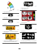
Safety and Instructional Decals Safety decals and instructions are easily visible to the operator and are located near any area of potential danger. Replace any decal that is damaged or missing. decal119-6854 119-6854 decal119-6809 119-6809 1. Floor speed 1. Read the Operator's Manual for instructions on cleaning the machine. decal119-6853 119-6853 1. Spinner speed decal115-2047 115-2047 1. Warning—do not touch the hot surface. decal119-6808 119-6808 decal119-0217 119-0217 1.
decal119-6810 119-6810 1. Read the Operator's Manual. 2. 2 people required to lift. decal119-6820 119-6820 1. Spinner speed adjustment decal119-6855 119-6855 1. Spinner speed decal119-6817 119-6817 1. Fine tuning spinners decal119-6856 119-6856 1. Floor speed decal119-6816 119-6816 decal119-6804 119-6804 1. Slide adjustment 1. Thrown object hazard—keep bystanders a safe distance from the machine. decal119-6805 decal119-6815 119-6805 119-6815 1.
decal119-6814 119-6814 3. Warning—slide adjustment and tailgate adjustment. 1. Light spread spinner adjustment settings (refer to the Operation section for more information). 2. Heavy spread spinner adjustment settings (refer to the Operation section for more information). decal119-6806 119-6806 1. Warning—read the Operator's Manual. 2. Warning—do not operate the machine unless you are trained. 4.
Setup Loose Parts Use the chart below to verify that all parts have been shipped. Procedure Description 1 2 3 4 5 6 7 8 Use Qty. Hopper guard Button head bolt (1/4 x 5/8 inch) Locknut Power harness Socket bracket Socket bracket, heavy Carriage screw Flange nut Screw Flange nut Hopper extension (front) Hopper extension (rear) Bolt Flange nut Bolt Flange nut 1 3 3 1 1 1 2 2 2 2 1 1 9 9 6 6 Intermediate wire harness 1 Connect the intermediate wire harness.
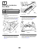
1 Setting Up the Machine Base Model Parts needed for this procedure: 1 Hopper guard 3 Button head bolt (1/4 x 5/8 inch) 3 Locknut g013204 Figure 4 Procedure 1. Shipping bracket 1. Remove the base model machine from the shipping crate. 2. At the rear of the twin spinner, remove the bolt and nut attaching the machine lifting device shipping bracket to the twin spinner (Figure 3). 4.
2 Installing the Power Harness Parts needed for this procedure: g013207 Figure 6 1. Packing studs and foam 6. Install the hopper guard using the supplied button-head bolts (1/4 x 5/8 inch) and nylon locknuts (Figure 7). 1 Power harness 1 Socket bracket 1 Socket bracket, heavy 2 Carriage screw 2 Flange nut 2 Screw 2 Flange nut Procedure The tow vehicle power harness provides the electrical power required by the control systems of the machine.
3 Installing the Hopper Extension Kit Parts needed for this procedure: g013261 1 Hopper extension (front) 1 Hopper extension (rear) 9 Bolt 9 Flange nut Figure 8 1. Socket bracket 2. Procedure 1. Route and secure the electrical wiring from the battery to the electrical plug bracket (Figure 9). Remove the hopper extensions from the box and identify the front and the rear (Figure 10 and Figure 11). g013263 Figure 10 1. Front hopper extension (showing hole orientation) g013262 Figure 9 1.
g237533 Figure 12 Hopper extension kit installed g013209 Figure 13 1. Lifting bracket 4 WARNING Do not attempt to lift the bed and hopper with the Tow-Behind Chassis, ProGator, Workman, or TDC Chassis connected. The lifting bracket is not capable of lifting the entire machine. Mounting the Hopper to the Tow Chassis Tow Chassis Configuration Only Parts needed for this procedure: 6 Bolt 6 Flange nut 2. Using a lifting mechanism, position the hopper over the tow chassis. 3.
5 6 Connecting the Intermediate Wire Harness Connecting the On/Off Pendant Parts needed for this procedure: Model 44701 Only 1 Intermediate wire harness Parts needed for this procedure: 1 Procedure Plug the intermediate wire harness into the power harness connector on the machine (Figure 15 or Figure 16). On/off pendant Procedure Plug the on/off pendant connector into the connector on the machine (Figure 17). g237534 Figure 15 Model 44751 1. Power harness g013947 Figure 17 2.
7 4. Secure the cover with 6 screws (Figure 18) and torque them to 1.5 to 1.7 N∙m (13 to 15 in-lb). 5. Install the handheld remote into the magnetic remote bracket, slide the halves together to secure the remote, and tighten the bolt in the magnet (Figure 19). Assembling the Handheld Remote Model 44751 Only Parts needed for this procedure: 1 Handheld remote 4 AA batteries 1 Magnetic bracket 6 Screws, small Procedure 1. 2.
Product Overview Controls Flow Control Valve for Floor Model 44701 Only A hydraulic flow control valve controls the speed of the conveyor belt. The highest speed setting is 10 and is typical for most applications found on the Color-Coded Operation System decals. Use lower settings for very light applications. g030466 Figure 20 Workman Heavy Duty Vehicle Shown 1. Remote 2. Controller mount assembly g013344 Figure 21 1.
A hydraulic flow control valve controls the speed of the option (Twin Spinner). The spinner icon indicates the speed percentage for the wireless controller only—for standard hydraulics, place the control in the appropriate color area, starting at the dotted line and adjust speeds within the color zone as required. On/Off Pendant Model 44701 Only Use the 2 switches on the On/Off pendant to run the conveyor belt or the option (Figure 23). Keep the On/Off pendant within reach of the operator.
Handheld Remote Specifications Model 44751 Only Weights Base Model 248 kg (546 lb) Twin Spinner 68 kg (150 lb) Radio Frequency 2.4 GHz Max Output Power 19.59 dBm Attachments/Accessories A selection of Toro approved attachments and accessories is available for use with the machine to enhance and expand its capabilities. Contact your Authorized Service Dealer or Distributor or go to www.Toro.com for a list of all approved attachments and accessories.
Connecting the Machine to a Tow Vehicle Operation Before Operation Safety WARNING • The machine has different balance, weight, and • • • • • • • • handling characteristics compared to some other types of towed equipment. Read and understand the contents of this Operator's Manual before operating the machine. Become familiar with all controls and know how to stop quickly. Never allow children or untrained people to operate or service the machine.
Turning the Machine Power On/Off When finished working with the machine, always press the E-STOP button (Figure 27) to disable the electrical system. When beginning work with the machine, you must pull the E-STOP button back out before turning on the handheld remote. g237530 Figure 27 1. E-STOP Button Important: When done operating the machine, press the E-STOP button to prevent the tow vehicle battery from being discharged.
Preparing the Machine for Operation The machine features a unique color-coded operation system that takes the guess-work out of setting up your machine. Simply choose the spread, identify the color, and then adjust each setting to match that color to get a perfect spread every time. Choosing the Spread Choose the spread by reading the main operation decal found on the tailgate of the machine (Figure 28). decal119-6814 Figure 28 1. Light spread spinner adjustment settings 3.
Setting the Tailgate, Spinner Speed, Slide, and Floor Speed Once you have selected the desired spread and ensured that the blades are properly adjusted, set the rest of the machine adjustments. g013699 Figure 33 Tailgate Decal Symbol Each setting is indicated on the machine by corresponding color decals (Figure 32). The 5 inch tailgate is divided into colors with a target starting line in each color section (Figure 34).
Standard Hydraulics (Model 44701): Set the hydraulic control to the dotted start line in the corresponding color area (Figure 36). You can vary the speeds if required within the corresponding color section. g013709 Figure 38 Slide Decal Symbol g013707 Figure 36 g013710 Figure 39 Wireless Control (Model 44751): Set according to the percentage indicated in the colored section of the decal and on the chart on the back of the wireless controller (Figure 37).
– Watch for holes or other hidden hazards. To correct this, the base setting adjustment has an illustration indicating the correct re-positioning of the base (Figure 41). – Use caution when operating on a steep slope. Travel straight up and down slopes. Reduce speed when making sharp turns or when turning on hillsides. Avoid turning on hillsides whenever possible. – Use extra caution when operating on wet surfaces, at higher speeds or with a full load. Stopping time increases with a full load.
• • • • • • • • – Be careful when turning and avoid unsafe maneuvers. – Always ensure that the machine is connected to the tow vehicle before loading. – Do not put large or heavy objects into the hopper. This could damage the belt and rollers. Also ensure that the load has a uniform texture. Small rocks in the sand can become projectiles. Do not stand behind the machine when unloading or spreading. The twin spinner, cross conveyor, and processor can eject particles and dust at a high speed.
Note: For wireless models the ALL START 2. function can be used in place of the OPTION START and FLOOR START functions as a single operation start feature. The option will start followed by the belt. Engage the parking brake on the tow vehicle, shut off the engine, and remove the key. 3. Place blocks under 2 wheels of the machine (front and back). Travel in a straight line and spread the material at a constant speed until the spread reaches the edge of the top dressing area. 4.
Handheld Remote g029772 Figure 42 1. LCD display 10. Floor Start 2. Remote status LED 11. Floor Stop 3. All Start: starts floor and option 12. Decrease floor speed 4. On/Off 13. Increase floor speed 5. Store: saves preset settings 14. Option start 6. Preset 1 15. Option stop 7. Preset 2 16. Increase option speed 8. Preset 3 17. Decrease option speed 9. All Stop: stops all functions Button Functions Button Name Primary Function ON/OFF Power the remote on and off.
Button Name Primary Function FLOOR INC Increases the floor speed. PRESET 1 PRESET 2 PRESET 3 Three separate preset values may be stored for both floor and option speeds. STORE Used in conjunction with the PRESET button to store or establish a preset memory. OPTION START Provides functional control of the rear option including on/off and displaying the option speed. OPTION STOP Stops the option. OPTION DEC Decreases the option speed. OPTION INC Increases the option speed.
Key Functionality Elements • When you turn the handheld remote on, the display should read FLR OFF and OPT OFF in approximately 5 seconds. If the words “waiting for base” are in the display, check to ensure there is electrical power to the base unit and ensure the E-STOP button on the base unit is out. • There is always a current working memory. This decal119-6815 Figure 44 Manual Override Decal 1. Floor speed adjustment is not the same as a preset.
Using the Liquid Crystal Display (LCD) backlighting increases power consumption and will shorten the life span of the batteries; the lower the backlighting, the longer the battery life span. The 2 line, 8 character-per-line LCD (Liquid Crystal Display) shows status and activity as the remote buttons are pressed. It features user adjustable backlighting and contrast. Changes are saved in the remote current working memory.
Understanding the Remote Status LED The remote status LED blinks slowly at 2 Hz (twice per second) when the handheld remote is transmitting but no buttons are being pressed, when the floor and option buttons active. When you press a button, the light will blink at 10 Hz. Replacing the Remote Batteries The handheld remote is powered by 4 batteries (size AA alkaline, 1.5 V each) and operates between 2.4 to 3.2 V.
Associating the Handheld Remote with the Base Battery Life, Operating Frequency, Base and Remote ID Display The factory initially associates the remote to the base allowing them to communicate; however, there may be instances in the field when you must reassociate a remote and a base unit, as follows: Hold down the ALL STOP and OPTION STOP buttons simultaneously to display multiple points of information. 1. Press the E-Stop button to remove power from the base unit and ensure that the handheld is off.
Note: Changes to the option settings while the change. The next time you use the remote, the setting will revert to the previously stored value. option is running are immediately effective, but they are temporary unless you store the new setting by pressing OPTION START again after changing the setting.
indicating that the remote is in a set-only mode. In this set-only mode, you can adjust either setting up or down, but the floor and option do not activate, remaining off. This allows you to set the desired speeds or use the stored settings without causing unwanted movement. After setting the speeds, press the ALL START button to activate the floor and option at the chosen setting (if the hydraulics are engaged, the floor and option will start).
Loading the Hopper then , , or WARNING The screen will display PRESET SAVED. Ensure that the machine is connected to the tow vehicle before loading. Note: If you hold the STORE button and press a PRESET button while either the floor or option are off, no new value is stored for either floor or option; the preset holds the values previously stored. Do not carry loads that exceed the load limits of the machine, or the tow vehicle; refer to Specifications (page 17). 1.
Parking the Machine WARNING Unloading the machine when it is not connected to the tow vehicle may cause the load to shift and the machine to tip over. Always park the machine on a level surface. Place blocks under 2 wheels of the machine (front and back if it is in the vehicle-mounted configuration). Ensure that the machine is connected to the tow vehicle before unloading. WARNING Disconnecting the machine from the tow vehicle on a slope could cause the machine to move unexpectedly.
g013338 Figure 48 g013777 Figure 49 1. Jack stands on Truckster Direct Connect 1. Rear jack stands 3. Locking pin 2. Front storage legs Using the Storage Stand 1. Park the work vehicle in the storage spot for the machine. Note: The storage spot must be a hard and 8. Using the vehicle lift cylinder, lower the front of the machine until the front storage stand legs begin to touch the ground. 9.
g013778 Figure 51 1. Lift cylinder locking pin 12. Store the cylinders in the storage clips. Engage the hydraulic lift lock lever on the vehicle to prevent accidental extension of the lift cylinders. 13. Raise the rear jack stands until enough clearance is attained to drive the vehicle away from the machine. 14. Walk around the machine. Ensure that it is clear of the work vehicle’s frame and secured within each of the 4 storage stand legs. 15.
Maintenance Several grease fittings are located on the machine and the tow-behind chassis (Figure 52, Figure 53 and Figure 54). Note: To obtain an electrical schematic or a hydraulic schematic for your machine, visit www.Toro.com. 1. Clean the grease fittings. 2. Pump the grease into the bearings and the bushings. 3. Clean off the excess grease. 4.
Hydraulic System Safety • Ensure that all hydraulic-fluid hoses and lines are in good condition and all hydraulic connections and fittings are tight before applying pressure to the hydraulic system. • Seek immediate medical attention if fluid is injected into skin. Injected fluid must be surgically removed within a few hours by a doctor. • Keep your body and hands away from pinhole leaks or nozzles that eject high-pressure hydraulic fluid. • Use cardboard or paper to find hydraulic leaks.
Adjusting the Conveyor Belt Tension Toro PremiumTransmission/Hydraulic Tractor Fluid (Available in 5 gallon pails or 55 gallon drums. See parts catalog or Toro distributor for part numbers.) Perform the tensioning procedure only if the belt is slipping, if it has been replaced, or if it has been loosened to replace other parts.
Washing the Machine track outside the grooves. To track the belt, do the following: 1. Determine which side the belt is tracking towards. 2. Remove the safety covers from both front corners. 3. On the side the belt is tracking towards, hold the end of the tensioner rod stationary, then loosen the locking nut and tighten the adjuster nut by 2 flats of the nut (Figure 55). 4. Tighten both locking nuts and turn on the conveyor belt. 5. Check the tracking movement.
9. Fully open the rear gate and spray water inside the hopper assembly and the rear gate area. Inspect the side seals and replace if necessary. 10. Locate the clean-out decal on the front of the machine (Figure 57), using a garden hose, spray through the front guard mesh until the belly pan is completely clear of material (Figure 58). Storage Before storing the machine for the season, do the following: 1. Thoroughly clean the machine. Remove parts if necessary.
Troubleshooting Checking Fault Codes (EH Models Only) If the Diagnostic LED indicates that there is a system fault (refer to Diagnostic LED Function (page 16)), check the fault codes to determine what is wrong with the machine. Entering Diagnostic Mode and Checking the Codes 1. Push the E-STOP button down to turn off the power. 2. Pull the tethered cap off of the 2 diagnostic shunt connectors (Figure 59, A). 3. Connect the diagnostic shunt connectors together (Figure 59, B). g238424 Figure 59 4.
Reseting the Fault Code After solving the problem, reset the fault codes by disconnecting and reconnecting diagnostic connectors. The diagnostic light will flash continuously at 1 Hz (1 flash per second). Exiting Diagnostic Mode 1. Push the E-STOP button down to turn off the power; refer to E-Stop Button (page 16). 2. Disconnect the diagnostic shunt connectors (Figure 59, B). 3. Push the tethered cap onto the 2 diagnostic shunt connectors (Figure 59, A). 4. Pull the E-STOP up to turn on the power.
Notes:
Notes:
European Privacy Notice The Information Toro Collects Toro Warranty Company (Toro) respects your privacy. In order to process your warranty claim and contact you in the event of a product recall, we ask you to share certain personal information with us, either directly or through your local Toro company or dealer. The Toro warranty system is hosted on servers located within the United States where privacy law may not provide the same protection as applies in your country.
The Toro Warranty A Two-Year Limited Warranty Conditions and Products Covered The Toro Company and its affiliate, Toro Warranty Company, pursuant to an agreement between them, jointly warrant your Toro Commercial product (“Product”) to be free from defects in materials or workmanship for two years or 1500 operational hours*, whichever occurs first. This warranty is applicable to all products with the exception of Aerators (refer to separate warranty statements for these products).