Form No. 3394-769 Rev A ProPass 200 Top Dresser Model No. 44701—Serial No. 315000001 and Up Model No. 44751—Serial No. 315000001 and Up Register at www.Toro.com.
model and serial numbers on the product. Write the numbers in the space provided. This product complies with all relevant European directives, for details please see the separate product specific Declaration of Conformity (DOC) sheet. Electromagnetic Compatibility Domestic: This device complies with FCC rules Part 15.
Contents Safety Safety ........................................................................... 3 Safe Operating Practices........................................... 3 Safety and Instructional Decals ................................. 6 Setup ............................................................................ 9 1 Setting Up the Machine Base Model ........................ 9 2 Installing the Power Harness..................................11 3 Installing the Hopper Extension Kit ..................
• – before clearing blockages; the job. Only use accessories and attachments approved by the manufacturer. Check that operators presence controls, safety switches, and shields are attached and functioning properly. Do not operate unless they are functioning properly. – before checking, cleaning, or working on the machine; – if the machine starts to vibrate abnormally (check immediately). • Disengage drive to attachments when transporting or not in use.
• Disengage drives, shift the transmission to Neutral, set parking brake, stop engine and remove key. Wait for all movement to stop before adjusting, cleaning or repairing. • Shut off fuel while storing or transporting. Do not store fuel near flames. • Park machine on level ground. Never allow untrained personnel to service machine. • Use jack stands to support components when required. • Carefully release pressure from components with stored energy. • Disconnect battery before making any repairs.
Safety and Instructional Decals Safety decals and instructions are easily visible to the operator and are located near any area of potential danger. Replace any decal that is damaged or lost. 119-6854 119-6809 1. Floor speed 1. Read the Operator's Manual for instructions on cleaning the machine. 119-6853 1. Spinner speed 115-2047 1. Warning—do not touch the hot surface. 119-6808 119-0217 1. Tailgate height indicator 1.
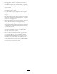
119-6810 1. Read the Operator's Manual. 2. Two people required to lift. 119-6820 1. Spinner speed adjustment 119-6855 1. Spinner speed 119-6817 1. Fine tuning spinners 119-6856 1. Floor speed 119-6816 119-6804 1. Slide adjustment 1. Thrown object hazard—keep bystanders a safe distance from the machine. 119-6805 119-6815 1. Cutting/dismemberment hazard, impeller—stay away from moving parts, keep all guards and shields in place. 1. Floor speed adjustment. 7 2. Spinner speed adjustment.
119-6814 3. Warning—slide adjustment and tailgate adjustment. 1. Light spread spinner adjustment settings (refer to the Operation section for more information). 2. Heavy spread spinner adjustment settings (refer to the Operation section for more information). 119-6806 2. Warning—do not operate the machine unless you are trained. 4. Warning—stop the engine, remove the ignition key and read the Operator's Manual before performing maintenance on the machine. 5. Warning—no riders on machine. 3.
Setup Loose Parts Use the chart below to verify that all parts have been shipped. Procedure Description 1 2 3 4 5 6 7 8 Use Qty.
1 Setting Up the Machine Base Model Parts needed for this procedure: 1 Hopper guard 3 Button head bolt, 1/4 x 5/8 inch 3 Lock nut Figure 4 Procedure 1. Shipping bracket 1. Remove the base model machine from the shipping crate. 4. This step requires two people. Lift the twin spinner out of the hopper using the twin spinner outer grab handles. Place the twin spinner unit on the ground (Figure 5). 2.
2 Installing the Power Harness Parts needed for this procedure: Figure 6 1. Packing studs and foam 1 Power harness 1 Socket bracket 1 Socket bracket, heavy 2 Carriage screw 2 Flange nut 2 Screw 2 Flange nut 6. Install the hopper guard using the supplied button head bolts (1/4 x 5/8 inch) and nylon locknuts (Figure 7). Procedure The tow vehicle power harness provides the electrical power required by the control systems of the machine.
3 Installing the Hopper Extension Kit Parts needed for this procedure: 1 Hopper extension-front 1 Hopper extension-rear 9 Bolt 9 Flange nut Figure 8 1. Socket bracket Procedure 1. Remove the hopper extensions from the box and identify the front and the rear (Figure 10 and Figure 11). 2. Route and secure the electrical wiring from the battery to the electrical plug bracket (Figure 9). Figure 10 1. Front hopper extension (showing hole orientation) Figure 9 1. White wire (brass) 3.
WARNING Do not attempt to lift the bed and hopper with the Tow-Behind Chassis, ProGator, Workman, or TDC Chassis connected. The lifting bracket is not capable of lifting the entire machine. 2. Using a lifting mechanism, position the hopper over the tow chassis. 3. Line up the 6 mounting holes (3 per side) and install the 5/16 x 1 inch bolts and flange nuts.
Figure 15 Model 44751 1. Power harness Figure 17 1. On/Off pendant 2. Intermediate wire harness 7 Assembling the Handheld Remote Model 44751 Only Parts needed for this procedure: Figure 16 Model 44701 1. Power harness 2. Intermediate wire harness 1 Handheld remote 4 AA batteries 1 Magnetic bracket 6 Screws, small Procedure 6 1. Remove the rubber bands securing the remote halves together, and remove the back cover. 2. Install the batteries into the terminal cradle observing proper polarity.
8 Mounting the Wireless Remote Model 44751 Only Parts needed for this procedure: 1 Controller mount assembly 1 Wireless remote assembly Procedure Insert the controller mount assembly into a cup holder or similar opening on the tow vehicle and use to store wireless remote. Also, the wireless remote magnet will stick to any metal component. Figure 18 1. Rubber seal 2. Steel gasket 3. Handheld remote 4. 4 AA batteries 3.
Product Overview On/Off Pendant Controls Model 44701 Only Use the two switches on the On/Off pendant to run the conveyor belt or the option (Figure 23). Keep the On/Off pendant within reach of the operator. Flow Control Valve for Floor Model 44701 Only A hydraulic flow control valve controls the speed of the conveyor belt. The highest speed setting is 10 and is typical for most applications found on the Color-Coded Operation System decals. Use lower settings for very light applications. Figure 23 1.
Specifications Weights Base Model 546 lb (248 kg) Twin Spinner 150 lb (68 kg) Attachments/Accessories A selection of Toro approved attachments and accessories are available for use with the machine to enhance and expand its capabilities. Contact your Authorized Service Dealer or Distributor or go to www.Toro.com for a list of all approved attachments and accessories. Figure 25 1. Diagnostic LED Handheld Remote Model 44751 Only Figure 26 1. LCD display 10. Floor Start 2. Remote status LED 11.
Operation the hoses, some machine functions may run backwards or not work at all. Test the hydraulics before operating the machine for the first time. Operating Characteristics Important: Do not allow the hydraulic lines, the power cable, and the pendant cables to drag on the ground. Avoid locations where they could become pinched or cut. The machine has balance, weight, and handling characteristics that may be different from other types of pulled equipment. Read this Operator’s Manual carefully. 7.
Setting-up the Machine for Operation The machine features a unique color-coded operation system that takes the guess-work out of setting up your machine. Simply choose the spread, identify the color, and then adjust each setting to match that color to get a perfect spread every time. Choosing the Spread Choose the spread by reading the main operation decal found on the tailgate of the machine (Figure 28). Figure 28 1. Light spread spinner adjustment settings. 3.
Setting the Tailgate, Spinner Speed, Slide, and Floor Speed Once you have selected the desired spread and ensured that the blades are properly adjusted, set the rest of the machine adjustments. Figure 33 Tailgate Decal Symbol Each setting is indicated on the machine by corresponding color decals (Figure 32). The 5 inch tailgate is divided into colors with a target starting line in each color section (Figure 34).
Figure 39 Figure 36 Note: The colors on the decal shown in Figure 39 correspond to the colors in the main operation decal (Figure 28). Wireless Control (Model 44751): Set according to the percentage indicated in the colored section of the decal and on the chart on the back of the wireless controller (Figure 37). Adjusting the Floor Speed The floor speed for every setting is usually 100%; this was developed and tested in order to have one less factor to adjust in the Color-Coded Operating System.
11. Travel in a straight line and spread the material at a constant speed until the spread reaches the edge of the top dressing area. 12. Turn off the conveyor belt, turn the machine around, and position it for the next pass. 13. Before making the next pass, check the spread pattern on the ground. Adjust the machine settings if necessary. 14. Continue steps 10 to 13 until the entire area requiring top dressing has been completed, or the hopper is empty Figure 41 15.
Handheld Remote 7. Lower the jack stand(s) as follows: • On tow-behind chassis, turn the jack stand 90 degrees (clockwise) to the down position to support the machine • On Truckster direct connect chassis, move the jack stands to the front of the machine and turn them 90 degrees until the bottom of both jack stands points to the ground. 8. Lift the machine with the jack stand(s) until the weight is off the tow-vehicle draw bar. Pull out the hitch pin. 9.
Button Name Primary Function FLOOR INC Increases the Floor speed. PRESET 1 PRESET 2 PRESET 3 Three separate preset values may be stored for both floor and option speeds. STORE Used in conjunction with the PRESET button to store or establish a preset memory. OPTION START Provides functional control of the rear option including on/off and displaying the option speed. OPTION STOP Stops the option. OPTION DEC Decreases the option speed. OPTION INC Increases the option speed.
Key Functionality Elements • When you turn the handheld remote on, the display should read FLR OFF and OPT OFF in approximately 5 seconds. If the words “waiting for base” are in the display, check to ensure there is electrical power to the base unit and ensure the E-STOP button on the base unit is out. • There is always a current working memory. This is not the same as a preset. The last saved work settings will be in the current working memory when you turn the handheld remote on.
Using the Liquid Crystal Display (LCD) Understanding the Remote Status LED The 2 line, 8 character-per-line LCD (Liquid Crystal Display) shows status and activity as the remote buttons are pressed. It features user adjustable backlighting and contrast. Changes are saved in the remote current working memory. When the unit is turned on after being powered down, the last settings for contrast and backlighting are used for the display.
Associating the Handheld Remote with the Base The factory initially associates the remote to the base allowing them to communicate; however, there may be instances in the field when you must reassociate a remote and a base unit, as follows: 1. Press the E-Stop button to remove power from the base unit and make sure the handheld is off. 2. Stand near the base unit in clear line of sight. 3. Simultaneously press and continue to hold the ON/OFF and the ALL STOP buttons.
Battery Life, Operating Frequency, Base and Remote ID Display 1. Press the FLOOR START button. Hold down the ALL STOP and OPTION STOP buttons simultaneously to display multiple points of information. The preview value and FLRS displays. + 2. Adjust the speed setting using the INCREASE FLOOR SPEED button or the DECREASE FLOOR SPEED button.
START again, storing the change. The next time you use the remote, the settings will revert to the previously stored values. enforced. The timer resets to ten seconds if any button is pressed while the remote is in the set-only. 1. Press the OPTION START button. Note: A 10 second timer starts when you press ALL START and set-only mode displays. If you do not press a button during the 10 second interval, the display reverts to FLR and OPT and the previous state/value displays and is enforced.
Tow Vehicle of an individual command using the FLOOR START or OPTION START buttons, and once in the event of a combined action using ALL START; in either case, it is the same number. WARNING Always use a suitable tow vehicle to move the machine, even for short distances. An unsuitable tow vehicle can damage the machine, or cause injury or death. Setting the Preset 1, 2, and 3 Buttons The override access is on the driver side of the hydraulic system.
Unloading If you have an option on the machine, be aware of the ground clearance when traveling on hills. When the machine begins to travel up a slope the ground clearance decreases. WARNING Keep hands and feet away from the hopper guard on the spinner guard and the spinner assembly when the machine is operating or when the hydraulic power pack engine, on the tow vehicle, is running. Parking Always park the machine on a firm, horizontal, and level surface.
Figure 48 Figure 49 1. Jack stands On Truckster Direct Connect 1. Rear jack stands 3. Locking pin 2. Front storage legs Using the Storage Stand 8. Using the vehicle lift cylinder, lower the front of the machine until the front storage stand legs begin to touch the ground. 1. Park the work vehicle in the storage spot for the machine. Note: The storage spot must be a hard and level surface. 9.
Figure 51 1. Lift cylinder locking pin 12. Store the cylinders in the storage clips. Engage the hydraulic lift lock lever on the vehicle to prevent accidental extension of the lift cylinders. 13. Raise the rear jack stands until enough clearance is attained to drive the vehicle away from the machine. 14. Walk around the machine. Ensure that it is clear of the work vehicle’s frame and secured within each of the four storage stand legs. 15.
Maintenance WARNING Disconnect all power sources to the machine before doing maintenance work. Note: Download a free copy of the schematics by visiting www.Toro.com and searching for your machine from the Manuals link on the home page. Figure 53 Lubrication 1. Grease fitting on Base Model (one at left rear, one at right rear) Lubricating the machine • Use an automotive, all-purpose grease. • Lubricate regularly, after 25 hours of normal operation.
Jack Stands Material Properties: Viscosity, ASTM D445 • Safely stow the jack stand(s) in the up position before traveling. On Truckster direct connect chassis stow the jack stands on the rear of the machine. cSt @ 40°C 55 to 62 cSt @ 100°C 9.1 to 9.8 140 to 152 Viscosity Index ASTM D2270 Pour Point, ASTM D97 -35°F to -46°F Industry Specifications: API GL-4, AGCO Powerfluid 821 XL, Ford New Holland FNHA-2-C-201.
WARNING Do not use flammable fluids or cleaners with toxic vapors. Follow the manufacturer’s recommendations. Important: Do not use a high-pressure washer. This can remove paint, safety decals, and grease, and can also damage components. 1. Remove the option before cleaning and wash it separately. 2. Remove hand held. 3. Wash the body of the machine with warm water and a mild detergent Figure 55 1. Locking nut 2. Adjuster nut 4. Completely rinse off the detergent residue with clean water before it dries.
Storage Before storing the machine for the season: 1. Thoroughly clean the machine. Remove parts if necessary. 2. Remove the hand held. Figure 57 3. Make sure the emergency stop button is pushed. 1. Clean Out Decal 4. Check all fasteners and tighten, if necessary. 5. Grease all fittings and pivot points. Wipe off any excess lubricant. 6. Lightly sand any painted areas that are scratched, chipped, or rusted, and apply touch-up paint. 7. Store the machine indoors, if possible. Figure 58 1.
Troubleshooting Checking Fault Codes (EH Models Only) If the Diagnostic LED indicates that there is a system fault (refer to Diagnostic LED Function (page 16)), check the fault codes to determine what is wrong with the machine. Entering Diagnostic Mode and Checking the Codes 1. Push the E-STOP button down to turn off the power. 2. Pull the tethered cap off of the two diagnostic, shunt connectors (Figure 59, A). 3. Connect the diagnostic, shunt connectors together (Figure 59, B). Figure 59 4.
Reseting the Fault Code After solving the problem, reset the fault codes by disconnecting and reconnecting diagnostic connectors. The diagnostic light will flash continuously at 1 Hz (1 flash per second). Exiting Diagnostic Mode 1. Push the E-STOP button down to turn off the power; refer to (page ). 2. Disconnect the diagnostic, shunt connectors (Figure 59, B). 3. Push the tethered cap onto the two diagnostic, shunt connectors (Figure 59, A). 4. Pull the E-STOP up to turn on the power.
Notes: 40
Notes: 41
Notes: 42
International Distributor List Distributor: Country: Phone Number: Distributor: Phone Number: 57 1 236 4079 Colombia Japan 81 3 3252 2285 Czech Republic 420 255 704 220 420 255 704 Slovakia 220 Argentina 54 11 4 821 9999 Russia 7 495 411 61 20 Ecuador 593 4 239 6970 Finland 358 987 00733 Agrolanc Kft Balama Prima Engineering Equip. B-Ray Corporation Hungary Hong Kong Korea 36 27 539 640 852 2155 2163 82 32 551 2076 Maquiver S.A. Maruyama Mfg. Co. Inc. Mountfield a.s.
The Toro Total Coverage Guarantee A Limited Warranty Conditions and Products Covered The Toro Company and its affiliate, Toro Warranty Company, pursuant to an agreement between them, jointly warrant your Toro Commercial product (“Product”) to be free from defects in materials or workmanship for two years or 1500 operational hours*, whichever occurs first. This warranty is applicable to all products with the exception of Aerators (refer to separate warranty statements for these products).