Form No. 3432-253 Rev A Toro® Workman® Chassis Mount Kit ProPass 200 Top Dresser Model No. 44707 Installation Instructions Safety Safety and Instructional Decals Safety decals and instructions are easily visible to the operator and are located near any area of potential danger. Replace any decal that is damaged or missing. decal119-6840 119-6840 1. Tipping hazard, loss of control—do not raise the hopper when filled; do not drive the vehicle while hopper is raised.
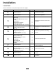
Installation Loose Parts Use the chart below to verify that all parts have been shipped. Procedure 1 2 Description Qty. Use No parts required – Prepare the machine. No parts required – Remove the cargo bed.
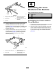
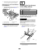
1 Preparing the Machine No Parts Required Procedure 1. Park the machine on a level surface. 2. Engage the parking brake. 3. Shut off the engine and remove the key. g038494 Figure 1 2 3 Removing the Cargo Bed Assembling the Rear and Center Cross Members No Parts Required Parts needed for this procedure: Procedure Remove the bed from the Toro Workman utility vehicle; refer to the Workman Operator's Manual. Note: Retain the cylinder pins for installing this kit.
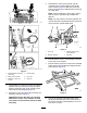
Assembling the Cross Members to the Machine Parts needed for this procedure: g288047 Figure 2 1. Flange locknut (3/8 inch) 4. Flange-head capscrew (3/8 x 2-1/2 inches) 2. Tube brace 5. Hinge bracket (rear cross member) 3. Loosely assemble a tube brace to the hinge bracket at the other end of the rear cross member (Figure 2) with 2 spacers, 2 flange-head capscrews (3/8 x 2-1/2 inches), and 2 flange locknuts (3/8 inch).
. Assemble the rods of the left and right lift cylinders to the cylinder plates of the center cross member (Figure 5) with the clevis pins and lynch pins that you retained when removing the cargo bed. Note: When installing the clevis pins, ensure that the 4 lynch pins are fully inserted and latched. Note: You may need to move the hydraulic lift cylinder forward or backward until the clevis pins line up with the cylinder plate holes. g288148 g288169 Figure 5 1. Lynch pin 3.
9. Check that the center cross member and the rear cross member are square and aligned. 5 Aligning the Front Cross Member to the Machine 1. Installing the Top Dresser to the Utility Vehicle Align the 2 L-bracket of the front cross member toward the front of the machine (Figure 7).
g288374 Figure 11 Left Side g288378 1. Rinse guard 5. Capscrew (5/16 x 3 inches) 2. Flange locknut (5/16 inch) 6. Left rail (top dresser) 3. Center cross member 7. 107.6 cm (42-3/8 inches) measurement 8. 112.7 cm (44-3/8 inches) measurement 4. Washer (5/16 inch) g288379 4. Loosely assemble the rail to the left side of the center cross member (Figure 11) with 2 capscrews (5/16 x 3 inches), 2 washers (5/16 inch), and flange locknut (5/16 inch). 5. At the right top-dresser rail, measure 103.
Assembling the Top Dresser to the Rear Cross Member 1. to the rail (Figure 15) with 2 capscrews (5/16 x 3 inches), 2 washers, and (5/16 inch), and 2 flange locknuts (5/16 inch). Measure 146.5 cm (57-11/16 inches) and 151.6 cm (59-11/16 inches) from the rinse guard to the holes in the rail (Figure 13). g288429 Figure 15 g288377 Figure 13 Right side shown (left side similar) 1. Flange locknut (5/16 inch) 4. Washer (5/16 inch) 2. Left rail (top dresser) 5. Front cross member 3.
Connecting the Hoses to the Control Valve Fittings Model 44701 1. At the valve mount, remove the caps from the T-fitting and the cross union fitting as shown in Figure 18. g288548 Figure 16 1. Bed support 2. Install the bed support (Figure 16) onto the cylinder rod; refer to the Operator's Manual for your utility vehicle. Removing the Top Dresser Hydraulic Guard Model 44701 g288550 1.
4. Route the hoses toward the forward right corner of the top dresser. 3. Connecting the Hoses to the Hydraulic Manifold Routing the Hydraulic Hoses Model 44751 1. Loosely assemble the 90° fitting of the return hydraulic hose (the hose with the arrow decal affixed) onto port-T of the hydraulic manifold (Figure 21). 1. Remove the caps from the from the union fittings at port-T and port-P of the hydraulic manifold (Figure 20).
3. Between the front and center cross members, route the hoses against the right frame rail (Figure 24). g288598 Figure 24 1. Right frame rail (top dresser) 4. g288547 2. Cable ties Figure 25 Secure the hoses to the holes in the frame rail with 2 cable ties (Figure 24). When attaching the hose, ensure that there is proper tension on the hoses. 1. Hopper (front wall) 4. Capscrew 2. Button-head screws 3. Valve mount 5. Washer 6. Hydraulic guard 2.
7 8 Installing Top Dresser Wire Harness and Optional Equipment Installing the Side Shields Parts needed for this procedure: No Parts Required 1 Left side shield 1 Right side shield 10 Flange-head capscrew (1/4 x 3/4 inch) 6 Flange locknut (1/4 inch) Procedure Important: When routing either the hydraulic Procedure hoses or the electrical wire harness, always make sure that you route them away from of all hot, sharp, or moving components and always ensure that there is no stress on the hoses or
9 Connecting the Hydraulic Hoses to the Vehicle No Parts Required Procedure g288617 Figure 27 Right side shield shown 1. Flange-head capscrews(1/4 x 3/4 inch) 4. Flange locknuts (1/4 inch) 2. Side shield 5. L-bracket (front cross member) 1. Remove bed support from the lift cylinder of the vehicle and stow the support. 2. Lower the top dresser onto the chassis of the vehicle. 3.
10 Completing the Chassis Mount Kit Installation No Parts Required Procedure 1. Remove the 4 button-head screws that secure the lifting bracket to the wall of the hopper (Figure 29). g288627 Figure 29 1. Lifting bracket 2. Button-head screw 2. Assemble the button-head screws into the wall of the hopper and tighten the screws (Figure 29). 3. For Model 44701, connect the On/Off pendant to the top dresser and place the pendant in the seating area of the vehicle.
Notes: