
Installation Instructions
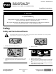
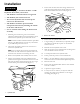
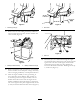

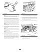
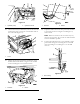


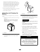
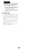

Figure12
1.Hydraulicpump
2.Hydraulichose#4
38.OntheSHversion,model44701,removethefasteners
securingthecovertothefrontoftheProPassandset
thecoveraside(Figure13).
Figure13
1.Cover
39.Identifythepressureandreturnconnectionsonthe
ProPassbasemodel.Referto
Figure14fortheSH
versionsandFigure15fortheEHversions.
G014215
Figure14
1.Pressure2.Return
Figure15
1.Pressure2.Return
40.Ifpressureandreturnhoseswerepreviouslyinstalled
atthelocationsshowninFigure14andFigure15,
removethem.
Note:Makesurethehosesdonotcontactanyhot,
sharpormovingparts.Trytoattainasmuchclearance
fromthemuferaspossible.
41.Connectthehydraulichosestothehydrauliccontrol
panel.RefertoFigure14andFigure16ontheSH
versionsandFigure15andFigure17ontheEH
versions.
Figure16
1.Hoserouting
6