
Installation Instructions


InstallingtheHydraulic
System
1.Unpackthehoseguide,hydraulicreturnhose
(hose#3),hydraulicsuctionhose(hose#4),4
bolts(1/4x3/4inch)and4locknuts(1/4inch).
Note:Removethehosesecuredtothehose
guide,hydraulicreturnhoseandhydraulic
suctionhoseforshipping.
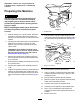
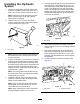
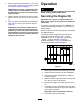
2.Using2bolts(1/4x3/4inch)andange
locknuts,attachthehoseguidetothebracket
onthehydraulictank(Figure9).
g013863
Figure9
1.Hoseguide
Note:Removethe2mountingboltsmustfrom
thechassisrearwall.Usetheremovedbolts
tomountthetank.
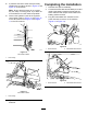
3.Unpack4bolts(3/8x1inch)andnylonlocknuts.
Supportingthehydraulictankfrombelow,pass
thehoseguideandhydraulichoses#3and#4
throughthelargecentralholeinthechassisrear
wallandlocatethehydraulictankagainstthe
chassisrearwall.T emporarilyclamp,orbolt,the
hydraulictankinplace.
Note:Thehoseguideshouldbefedthrough
thecenterholeonthefrontsideofthechassis.
2peoplemayberequired.
4.Installthehydraulicreturnhose(#3)andthe
hydraulicsuctionhose(#4)totheappropriate
ttingsonthehydraulictank.
Note:Hose#3andhose#4donothavethe
samettings;eachhosewilltonlyintothe
correctttinginthehydraulictank.
Note:Whenmountingthehoses,ensurethat
thereisadequateclearanceforthetires.
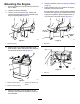
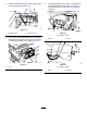
5.Thehoseguideshouldsitontopofthetabfrom
theverticallegofthebatterytray(Figure10).
Iftheholesinthehoseguidedonotmatchthe
holesinthebatterytraytab,thehoseguide
lengthmaybeadjustedbylooseningthebolts
attachingthehoseguidetothehydraulictank
bracketandslidingthehoseguideforwardor
totherearasrequired.
g013864
Figure10
1.Hoseguide
6.Attachthehoseguidetothebatterytraytab
using2bolts(1/4x3/4inch)andangelocknuts
(Figure10).
7.Mountthehydraulictanktothechassisrear
wallusingthepreviouslyremovedmounting
bolts,aswellasthebolts(3/8x1inch),nylon
locknuts,andatwashersfromthekit,Tighten
thefasteners.
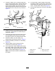
8.Connecthydraulichose#3tothelteroutlet
(Figure11).
g013865
Figure11
1.Filteroutlet
2.Hydraulichose#3
6