
Installation Instructions


g019164
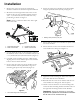
Figure13
1.Routinghydraulichoses
Figure14
1.Bolt,1/4x2–1/2inch
4.Hydraulichose
2.Washer
5.Flangelocknut,1/4inch
3.Tubeclamp
6.Clampplate
Important:Whenroutingeitherthehydraulic
hosesortheelectricalwiringharnessalways
makesuretoroutethemawayfromofall
hot,sharpormovingcomponentsandalways
ensurethatthereisnostressontheline.This
mayrequirelooseningandrepositioningthe
hydraulichoseatthefrontbulkhead.
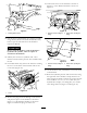
28.Betweenthefrontandcenterhoseclampsensurethat
thehosebendsupwardstoclearanycomponents.
Todothis,install2cabletiesaroundthepressure
andreturnhosesandattachittooneoftheProPass’
siderailmountingholes(Figure15).
g019165
Figure15
1.Ensurepropertensionofhydraulichoses
29.Connectthepressureandreturnhosestotheproper
hydraulicportsattherearoftheProGator.
30.Routeandconnecttheelectricalconnections.Refer
totheProPassOperatorsManualfortheinformation
ontheelectricalconnections.
Note:Iftheelectricalconnectionisinstallednear
thebatteryofthevehicle,makesuretoroutethe
electricalpowercordfromtheProPasstotheback
ofthevehicle,atthepivotlocation,thenforward
tothebattery.
Note:Iftheelectricalconnectionisinstalledatthe
rearofthetowvehicle,routeandsecuretheelectrical
powercordtothehydraulicpressureandreturn
hosesfromthefronttotherearoftheProPass.
31.Removetheliftcylindersafetybarfromthevehicle
andlowertheProPassbackdownontothechassis
oftheProGator.
32.Installtheoptionandconnectthehydraulichoses
totheProPass.
Note:Ensurethatthepressureandreturnhoses
areattachedtotherearoftheProGatoranddonot
comeincontactwiththeoption.
33.Usingthecurvedclampendofthewirelessmounting
assembly,looselysecureittotheleftendofthe
handholdtubewith(4)boltsandnutsshipped
withtheassembly.Positionthebracketasshown
in(
Figure16).
5