
Installation Instructions


2.Removeaknockoutplugfromanavailable
switchlocationonthedash.
Ifnoswitchlocationsareavailable,installthe
switchbracketasfollows:
A.Findanemptyspaceonthedashto
accommodatetheswitchbracket,anddrill
2holes(7mmor9/32inch)inthedash.
Note:Usetheswitchbracketasaguide
fordrillingtheholes.
B.Mounttheswitchbrackettothedashusing
the2boltsand2angenuts(Figure9).
g031586
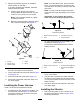
Figure9
1.Bolt(2)4.Switch
2.Flangenut(2)
5.Decal
3.Switchbracket
3.Inserttheswitch,withtheroundedsideup,into
theholeinthedashorintothebracket.
4.Connecttheswitchharnesstotheswitch(Figure
9andFigure11).
5.Placethedecalnexttotheswitch(Figure9).
6.Securetheharnesswithcableties,awayfrom
anysharpedges.
InstallingthePowerHarness
Install1ofthepowerharnessesasfollows:
1.Topowerthekitfromthetractorfuseblock,use
thefuse-blockharnessFigure10.Attachthe
fuse-blockconnectortothetractorfuseblock
andinstalla15Afuse.
Note:Ifthefuseblockisfull,addanewfuse
block,connectthefuse-blockconnectortothe
newfuseblock,thenadda15Afusetothenew
fuseblock.
Note:Youmayneedtochangetheterminal
and/orthewirelength,dependingonthetractor
model.
Important:Ifyoulengthentheharness,
makesuretousethepropergaugeofwire.
g031581
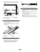
Figure10
Fuse-blockharness
1.Switch-harnessconnector
3.Fuse-blockconnector
2.Fuse
4.Groundterminal
Topowerthekitdirectlyfromthebattery,use
thebatteryharness(Figure11).
Connectthepositiveterminaltothepositive
batteryterminal.
g031582
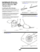
Figure11
Batteryharness
1.Switch-harnessconnector3.Positiveterminal(redwire)
2.Fuse
4.Groundterminal(black
wire)
2.Connectthegroundingterminaltotheground
blockofthevehicle.
3.Plugtheopenconnector(theswitch-harness
connector)onthepowerharnessintotheopen
connector(thepower-harnessconnector)onthe
switchharness.
4.Securetheharnesswithcableties,awayfrom
anysharpedges.
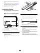
InstallingtheVibrator
1.Drill4mountingholes(7mmor9/32inch)on
thesideofthehopper.RefertoFigure12for
thedrillingdimensions.
4