
Installation Instructions


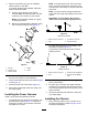


Note:Locate1hole,thenusethemounting
plateasatemplatefordrillingtheremaining
holes.
g031587
Figure12
1.4.1cm(1-5/8inches)4.12.7cm(5inches)
2.76.2cm(30inches)5.9.1cm(3-5/8inches)
3.Hole(7mmor9/32inch)
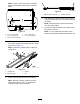
2.Securethemountingplateandthevibratorto
thevehicleusingthe4carriageboltsand4nuts
asshowninFigure13.
Note:Positionthevibratorcablesothatitis
facingdown.
g024368
Figure13
1.Carriagebolt
3.Vibrator
2.Mountingplate
4.Nut
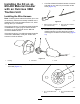
3.Connectthevibratorharnesstothevibrator.
Note:Routethevibratorharnesssothatit
followsthehydrauliclines,astheMH-400
materialhandlercanpivotupward.
g031585
Figure14
1.Switch-harnessconnector
2.Vibratorconnector
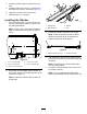
4.Usecabletiestosecureallthewiresalongthe
hydrauliclinesallthewaytotheswitch-harness
connector.
Note:Ensurethattheharnessiskeptaway
fromanysharpedges.
5.Connecttheswitchharnesstotheotherendof
thevibratorharness.
Note:Youcanmaketheconnectionwhen
attachingthematerialhandlertothetractionunit.
5