
Setup Instructions


2
InstallingtheLiftArm
Assembly
Partsneededforthisprocedure:
1
Liftarmassembly
Procedure
1.Removetheseatpanboltandiptheseatpanup.
2.Removethetophalfoftheclampsonthebasethen
feedtheliftarmassemblyundertheseatsupport.
Note:Ensurethatthepositionoftheliftarmis
centeredbetweentheangesweldedtotheshaftas
theytinsidetheliftarmclamps.
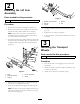
3.Installthetophalfoftheclampsandsecurethemwith
thepreviouslyremovedbolts.Donottightenthebolts
completelyuntilthegasliftramhasbeeninstalled
(Figure2).
1
2
3
4
5
G018763
Figure2
1.Bolts
4.Liftarmassembly
2.Nutsandwashers
5.Clamp
3.Clamps
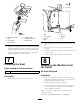
4.Removethenutsandwashersontheendofthegas
ramthatisnotassembledtothebase.
5.Placetheshoulderendthroughtheliftarmtophole.
Note:Theboltsintheclampsholdingtheliftarmin
placemayneedtobeloosenedtoeasilylocatethegas
raminthearm(Figure3).
1
2
3
4
5
G018764
Figure3
1.Shoulderendofgasram
4.Washer
2.Gasram
5.Nut
3.Liftarm
6.Installthewashersandnutontheothersideofthe
gasram.
7.Tightenthenutusingtwospanners.
8.Torquetheboltsontheliftarmassemblyto47.5N-m
(35ft-lb).
3
InstallingtheTransport
Wheels
Partsneededforthisprocedure:
2Transportwheels
Procedure
1.Placetheliftarmintheuprightpositiontoraisethe
wheelhubs.
2.Installthetransportwheels.Torquethewheellugnuts
to108N-m(80ft-lb).
3.Adjustthetirepressureto0.65bar(10psi).
2