PART NO. 12193SL Service Manual GreensPro™ 1200 Preface The purpose of this publication is to provide the service technician with information for troubleshooting, testing, and repairing assemblies and components on the GreensPro 1200. REFER TO THE OPERATOR’S MANUAL FOR OPERATING, MAINTENANCE, AND ADJUSTMENT INSTRUCTIONS. Space is provided in Chapter 2 of this book to insert the Operator’s Manual and Parts Catalog for your machine. Replacement catalogs are available on the Internet at www.toro.com.
This page is intentionally blank.
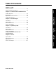
Table Of Contents Chapter 2 - Product Records and Maintenance Product Records ...................................................... 2-2 Maintenance ............................................................ 2-2 Equivalents and Conversions .................................. 2-3 Torque Specifications .............................................. 2-4 Chapter 3 - Gasoline Engine Introduction .............................................................. 3-2 Specifications...................................
This page is intentionally blank.
Chapter 1 Safety Safety Safety Table of Contents Safety Instructions ........................................ 1-2 Before Operating ................................................ 1-2 While Operating.................................................. 1-2 Maintenance and Service ................................... 1-3 Safety and Instruction Decals ......................
Safety Instructions GreensPro 1200 machines have been tested and certified by Toro for compliance with existing safety standards and specifications. Although hazard control and accident prevention are partially dependent upon the design and configuration of the machine, these factors are also dependent upon the awareness, concern, and proper training of the personnel involved in the operation, transport, maintenance, and storage of the machine.
1. The Operator’s Manual and engine Owner’s Manual provide information regarding the operation, general maintenance, and maintenance intervals for your GreensPro machine. Refer to these publications for additional information when servicing the machine. 2. Before servicing or making adjustments to the machine, stop the engine and wait for all machine motion to stop. Remove the spark plug wire from the spark plug to prevent accidental starting of the engine.
Safety and Instruction Decals Safety decals and instructions are easily visible to the operator and are located near any area of potential danger. Replace any decal that is damaged or lost. Decal part numbers are listed in your Parts Catalog. Order replacement decals from your Authorized TORO Distributor.
Chapter 2 Product Records and Maintenance Product Records and Maintenance Table of Contents Product Records and Maintenance Product Records ............................................ 2-2 Maintenance ................................................... 2-2 Equivalents and Conversions ...................... 2-3 Decimal and Millimeter Equivalents.................... 2-3 U.S. to Metric Conversions ................................. 2-3 Torque Specifications ...................................
Product Records Insert Operator’s Manual and Parts Catalog for your GreensPro 1200 at the end of this section. In addition, if any optional equipment or accessories have been installed to your machine, insert the Installation Instructions, Operator’s Manuals, and Parts Catalogs for those options at the end of this chapter. Maintenance Maintenance procedures and recommended service intervals for the GreensPro 1200 are covered in the Operator’s Manual.
Equivalents and Conversions Decimal and Millimeter Equivalents Decimals 0.015625 0.03125 1/32 3/64 0.046875 1/16 0.0625 5/64 0.078125 3/32 0.09275 7/64 0.109375 0.1250 1/8 9/64 0.140625 0.15625 5/32 11/64 0.171875 3/16 0.1875 13/64 0.203125 7/32 0.21875 15/64 0.234375 1/4 0.2500 17/16 0.265625 0.28125 9/32 19/64 0.296875 5/16 0.3125 21/64 0.328125 11/32 0.34375 23/64 0.359375 0.3750 3/8 25/64 0.390625 0.40625 13/32 27/64 0.421875 7/64 0.4375 29/64 0.453125 0.46875 15/32 31/64 0.484375 0.5000 1/2 1 mm = 0.
Torque Specifications Recommended fastener torque values are listed in the following tables. For critical applications, as determined by Toro, either the recommended torque or a torque that is unique to the application is clearly identified and specified in this Service Manual. These Torque Specifications for the installation and tightening of fasteners shall apply to all fasteners that do not have a specific requirement identified in this Service Manual.
Standard Torque for Dry, Zinc Plated, and Steel Fasteners (Inch Series Fasteners) Grade 1, 5, & 8 with Thin Height Nuts SAE Grade 1 Bolts, Screws, Studs, & Sems with Regular Height Nuts (SAE J995 Grade 2 or Stronger Nuts) in--lb in--lb 10 + 2 13 + 2 N·m in--lb # 6 -- 32 UNC # 8 -- 32 UNC 25 + 5 # 10 -- 24 UNC 30 + 5 in--lb N·m 15 + 2 1.69 ± 0.23 23 + 3 2.62 ± 0.34 17 + 2 1.92 ± 0.23 25 + 3 2.82 ± 0.34 29 + 3 3.28 ± 0.34 41 + 5 4.63 ± 0.56 31 + 4 3.5 ± 0.45 43 + 5 4.86 ± 0.
Standard Torque for Dry, Zinc Plated, and Steel Fasteners (Metric Fasteners) Thread Size Class 8.8 Bolts, Screws and Studs with Regular Height Nuts (Class 8 or Stronger Nuts) Class 10.9 Bolts, Screws and Studs with Regular Height Nuts (Class 10 or Stronger Nuts) M5 X 0.8 57 + 6 in--lb 6.44 ± 0.68 N·m 78 + 8 in--lb 8.81 ± 0.90 N·m M6 X 1.0 96 + 10 in--lb 10.85 ± 1.13 N·m 133 + 14 in--lb 15.03 ± 1.58 N·m M8 X 1.25 19 + 2 ft--lb 26 + 3 N·m 28 + 3 ft--lb 38 + 4 N·m M10 X 1.
Other Torque Specifications SAE Grade 8 Steel Set Screws Wheel Bolts and Lug Nuts Thread Size Recommended Torque Recommended Torque** Square Head Hex Socket 1/4 -- 20 UNC 140 + 20 in--lb 73 + 12 in--lb 5/16 -- 18 UNC 215 + 35 in--lb 145 + 20 in--lb 3/8 -- 16 UNC 35 + 10 ft--lb 18 + 3 ft--lb 1/2 -- 13 UNC 75 + 15 ft--lb 50 + 10 ft--lb 7/16 -- 20 UNF Grade 5 65 + 10 ft--lb 88 + 14 N·m 1/2 -- 20 UNF Grade 5 80 + 10 ft--lb 108 + 14 N·m M12 X 1.25 Class 8.
This page is intentionally blank.
Chapter 3 Gasoline Engine Gasoline Engine Table of Contents Introduction .................................................... 3-2 Operator’s Manual .............................................. 3-2 Engine Identification ........................................... 3-2 Specifications ................................................ 3-3 General Information....................................... 3-4 Fuel Evaporative Control System ....................... 3-4 Service and Repairs ............................
Introduction Detailed information on engine operation, general maintenance, maintenance intervals, and adjustments is given in the Honda GX200 Owner’s Manual. This chapter gives information about specifications and repair of the Honda GX200 gasoline engine used in the GreensPro 1200. Described adjustments and repairs require tools that are commonly available in many service shops.
Specifications Item Description Make Honda, 4-stroke, OHV, Single Cylinder, Air-Cooled, Gasoline Engine, GX2000 Bore x Stroke 2.68 in. x 2.13 in. (68.0 mm x 54.0 mm) Total Displacement 12.0 cu. in. (196 cc) Carburetor Float Feed Fixed Main Jet Governor Mechanical Flyweight Idle Speed (no load) 1250–1600 rpm High Idle (no load) 3200 rpm Direction of rotation Counterclockwise (Facing PTO Shaft) Fuel Unleaded Automotive Grade Gasoline 3.3 U.S. Quarts (3.
General Information Fuel Evaporative Control System (Figure 1.) To meet worldwide emission standards, the engine that powers your GreensPro is equipped with a fuel cap that has an integrated carbon canister. This fuel cap captures fuel vapors from the fuel tank prior to venting to atmosphere. 1 Figure 1 To prevent saturating the carbon canister in the fuel cap, it is important to make sure that the fuel tank is not overfilled.
Service and Repairs Engine 6. Remove rear support frame (5). Removal (Figures 2 through 8.) 1. Park machine on a clean, level surface with the transport wheels in the raised and locked position. Make sure engine is OFF. Remove spark plug wire from the spark plug. 2. Close the fuel shutoff valve. 3. Remove transmission cover from machine (see Transmission Cover in the Service and Repairs section of Chapter 5 - Chassis). Gasoline Engine 9 10 11 Figure 4 1 2 3 4 Figure 2 4.
19 12 13 14 15 20 22 21 23 24 Figure 6 25 9. Remove two lock nuts (13), flat washers (14), and cap screws (15), and remove drive coupling (12). Figure 8 NOTE: Machines with serial numbers above 313000000 include an engine that has a different output shaft and collar than earlier machines. Use the procedure that matches your engine collar assembly. 19. Engine (machine serial number above 313000000) 20. Square key 21. Engine shaft spacer 22. Engine collar 23. Flat washer 24. Lock washer 15 25.
Installation (Figures 9 through 15.) NOTE: Machines with serial numbers above 313000000 include an engine that has a different output shaft and collar than earlier machines. Use the procedure that matches your engine collar assembly. 5 1 6 8 7 9 10 11 2 Figure 10 3 Gasoline Engine 5. Engine (machine serial number above 313000000) 6. Square key 7. Engine shaft spacer 4 8. Engine collar 9. Flat washer 10. Lock washer Figure 9 11. Socket-head cap screw 1.
16 17 18 23 24 25 26 Figure 12 Figure 15 6. Connect the drive coupling to the engine collar using two nuts (23), two washers (24), two cap screws (25), and four spacers (26). IMPORTANT: To prevent drive coupling damage, make sure that no distortion of coupling exists after securing engine collar to coupling. If coupler distortion is evident, loosen engine and reposition engine on frame so that coupling is not distorted. 16 17 18 7.
Chapter 4 Hydraulic System Hydraulic System Table of Contents Introduction .................................................... 4-2 Specifications ................................................ 4-3 General Information....................................... 4-5 Hydraulic Hoses ................................................. 4-5 Hydraulic Fitting and Hose Installation ............... 4-5 Using a Torque Wrench with an Offset Wrench . 4-6 Relieving Hydraulic System Pressure ................
Introduction Some service and repair parts for the transmission in your GreensPro machine are supplied through your Authorized TORO Distributor. Be prepared to provide your distributor with the TORO model and serial number of your machine to obtain parts. When disposing of hazardous waste products, take them to an authorized disposal site. Waste products must not be allowed to contaminate surface water, drains, or sewer systems.
Specifications Item Description Hydro-Gear Hydrostatic Transmission Transmission (Model BDR) Pump Displacement (per revolution) 0.62 in3 (10.2 cc) Motor Displacement (per revolution) 1.33 in3 (21.8 cc) Hydraulic Tank Capacity 5.3 U.S. Quarts (5.
This page is intentionally blank.
General Information Hydraulic Hoses Hydraulic hoses are subject to extreme conditions such as pressure differentials during operation and exposure to weather, sun, chemicals, very warm storage conditions, or mishandling during operation or maintenance. These conditions can cause damage or premature deterioration. Some hoses are more susceptible to these conditions than others. Inspect the hoses frequently for signs of deterioration or damage.
Using a Torque Wrench with an Offset Wrench (Figure 1.) Use of an offset wrench (e.g., crowfoot wrench) will affect torque wrench calibration due to the effective change of torque wrench length. When using a torque wrench with an offset wrench, multiply the listed torque recommendation by the calculated torque conversion factor (Figure 1) to determine proper tightening torque. Tightening torque when using a torque wrench with an offset wrench will be lower than the listed torque recommendation.
Relieving Hydraulic System Pressure Before disconnecting or performing any work on the GreensPro 1200 hydraulic system, all pressure in the hydraulic system must be relieved. Park machine on a level surface. Make sure engine is OFF. To relieve hydraulic pressure in the traction circuit, depress each of the motion pedals fully. Traction Circuit Component Failure The GreensPro 1200 traction circuit includes the transmission, oil tank, and oil filter.
Service and Repairs Transmission Removal (Figures 2 through 7.) 1. Park machine on a clean, level surface with the transport wheels in the raised and locked position. Make sure engine is OFF. Remove spark plug wire from the spark plug. 4 5 2. Move motion pedals to relieve system pressure. 6 3 3. Remove transmission cover from machine (see Transmission Cover in the Service and Repairs section of Chapter 5 - Chassis). 9 4. Drain oil from oil tank into a suitable container. 7 6 8 Figure 3 2 8.
27 28 29 31 32 27 28 29 27 28 29 30 14 15 16 Figure 5 11. Remove lock nut (14), cap screw (15), and two flat washers (16) at the bottom of the transmission. 12. Support the transmission. Figure 7 15. Remove the retaining ring (31). 16. Remove three lock nuts (27), three cap screws (28), and six flat washers (29), and pull transmission (32) back until the two 8-tooth sprockets (30) are free of the shaft. 17 18 Hydraulic System 17. Remove transmission (32). 25 26 19 24 22 23 21 20 Figure 6 13.
Disassembly Assembly (Figures 8 and 9.) (Refer to Figures 8 and 9.) 1. Install damper plate (11), two flat washers (9), spacer (8), cap screw (10), and lock nut (12). 2 3 1 2. Install straight fitting (13) and O-ring (14). Tighten fitting to 26 lb-ft (35 N·m). 3. Install straight fitting (6) and O-ring (7). Tighten fitting to 26 lb-ft (35 N·m). 4 4. Place transmission fan (3) and fan support ring (5) over the transmission input shaft. 5. Install key (4) in transmission input shaft. 6.
7 8 15 16 9 14 12 13 18 19 20 21 Figure 13 11 10 Figure 11 6. Install idler arm assembly (13) using cap screw (14), flat washer (12), pivot bushing (15), two Oilite® bushings (16), spacer (9), flat washer (7), and nut (8). 7. Install flat washer (11) and nut (10). NOTE: If additional chain tension adjustment is needed, nuts on tension rod can both be installed on side of frame bracket that is closest to machine centerline.
30 29 Figure 15 12. Remove plugs that were installed in hoses and fittings during the removal process. 13. Using labels placed during removal, attach oil hoses (29 and 30) to fittings on the transmission assembly. Tighten hose swivel nuts to 24 lb-ft (32 N·m). 14. Adjust drive chain tension and lubricate chain. (Refer to Operator's Manual.) Dri-Slide® Multi-Purpose Lubricant (or equivalent) is recommended for chain lubrication. After drive chain adjustment, the drive chain should have 0.200 in. to 0.
Transmission Service (Figure 16.) 7 48 4 36 5 37 210 to 270 in-lb (24 to 30 N·m) 6 40 8 33 49 1 50 180 to 220 in-lb (21 to 27 N·m) 51 34 9 52 10 11 25 24 16 41 14 525 to 700 in-lb (60-79 N·m) 15 26 29 42 to 62 in-lb (5 to 7 N·m) 3 21 16 17 53 13 38 42 31 12 Hydraulic System 28 35 30 39 27 50 37 20 22 18 23 19 32 135 to 185 in-lb (10 to 20 N·m) 2 44 43 45 47 87 to 108 in-lb (10 to 12 N·m) 46 47 Figure 16: Transmission 1. Upper housing assembly 10.
28. Retaining ring 37. Retaining ring (2 used) 46. Charge pump housing 29. Bearing retainer 38. Bypass plate 47. Cap screw (2 used) 30. Slot guide 39. Bypass actuator 48. Retaining ring 31. Trunnion arm 40. Seal 49. Return arm 32. Gasket 41. Seal 50. Washer (2 used) 33. Seal 42. Washer 51. Screw 34. Control arm 43. Cap screw (9 used) 52. Scissors arm assembly 35. Lock nut 44. O-ring 53. Extension spring 36. Bypass arm 45.
Drive Chain Tension Assembly 6. Remove cap screw (9), lock nut (13), and two flat washers (14), and remove tension rod (12) from idler arm (18). Removal (Figure 17.) 1. Park machine on a clean, level surface with the transport wheels in the raised and locked position. Make sure engine is OFF. Remove spark plug wire from the spark plug. 2. Remove drive chain tension assembly from machine (see Transmission in this section). Installation (Refer to Figure 17.) 1.
Oil Tank Removal (Figures 18 through 20.) 1. Park machine on a clean, level surface with the transport wheels in the raised and locked position. Make sure engine is OFF. Remove spark plug wire from the spark plug. 3 2. Move motion pedals to relieve system pressure. 3. Remove transmission cover from machine (see Transmission Cover in the Service and Repairs section of Chapter 5 - Chassis). 4. Drain hydraulic oil from oil tank into a suitable container. 4 4 5 5 6 6 1 Figure 19 8.
7 13 8 9 10 12 11 9 10 7. Cap 11. Seal 8. Oil tank 12. Drain plug 9. Seal (2 used) 13. Decal Hydraulic System Figure 20 10. Adapter fitting (2 used) 10. Remove two adapter fittings (10) and seals (9). 11. Remove drain plug (12) and seal (11).
Installation (Figures 21 through 23.) 8 1 7 9 10 11 2 3 9 10 11 4 Figure 22 6 5 3. Position oil tank assembly (8) on machine. Secure tank to chassis using two cap screws (9), two lock nuts (10), and four flat washers (11). 3 4. Remove plugs that were installed in hoses and fittings during the removal process. 4 Figure 21 1. Cap 5. Seal 2. Oil tank 6. Drain plug 3. Seal (2 used) 7. Decal 12 4. Adapter fitting (2 used) 1. Install drain plug (6) and seal (5). 2.
Oil Filter Assembly Removal 7 (Figures 24 and 25.) 1. Park machine on a clean, level surface with the transport wheels in the raised and locked position. Make sure engine is OFF. Remove spark plug wire from the spark plug. 8 2. Move motion pedals to relieve system pressure. 7 3. Remove transmission cover from machine (see Transmission Cover in the Service and Repairs section of Chapter 5 - Chassis). 4. Drain oil from oil tank into a suitable container. 5.
loose connections. Installation (Figures 26 and 27.) 1 2 1 Figure 26 1. Apply thread sealant tape to threads of straight fittings (1) that will be threaded into the oil filter assembly (2). 4 5 6 3 7 2 Figure 27 2. Install the oil filter assembly (2) onto bracket using two cap screws (4), lock washers (5), and flat washers (6). 3. Remove plugs that were installed in hoses and fittings during the removal process. 4.
Chapter 5 Chassis Chassis Table of Contents Specifications ................................................ 5-2 General Information....................................... 5-3 Operator’s Manual .............................................. 5-3 Steering Operation ............................................. 5-4 Traction Control Operation ................................. 5-5 Adjustments ................................................... 5-6 Lifting Bar Adjustment ........................................
Specifications Item Description Steering Wheel Bolt Torque 225 in-lb (25.4 N·m) Transport Wheel Lug Nut Torque 80 ft-lb (108 N·m) Transport Wheel Tire Pressure 10 psi (0.65 bar) Axle Clamp Bolt Torque 35 ft-lb (47.5 N·m) Tow Bar Clamp Bolt Torque 35 ft-lb (47.
General Information Operator’s Manual Chassis The Operator’s Manual provides information regarding the operation, general maintenance, and maintenance intervals for your GreensPro machine. Refer to the Operator’s Manual for additional information when servicing the machine.
Steering Operation (Figure 1.) 1 7 2 3 5 6 4 Figure 1 1. Rear steering head 4. Steering disc assembly 6. Steering pivot rod 2. Front steering head 5. Front steering head linkage arm 7. Steering pivot 3. Rear steering head linkage arm The GreensPro steering system includes a number of components that cause the front steering head (2) and rear steering head (1) to rotate when the steering wheel is turned by the operator. The rotation of the steering heads allows the machine to change direction.
Traction Control Operation (Figure 2.) 6 4 5 2 3 1 8 7 1. Traction roller 4. Pedal rod pivot 7. LH motion pedal 2. Quadrant lever 5. RH front traction link 8. LH front traction link 3. Rear traction link 6. RH motion pedal The GreensPro traction system uses two motion pedals connected to the hydraulic transmission control arm to control machine direction and speed.
Adjustments Lifting Bar Adjustment (Figures 3 and 4.) 1. Park machine on a clean, level surface with the transport wheels in the raised and locked position. Make sure engine is OFF. Remove spark plug wire from spark plug. 6. Connect lifting bar (3) to tow bar lever (2) using cap screw (4), washer (5), bushing (6), washer (7), and lock nut (8). Repeat for other side of machine. 7. Remove support from rear of machine. 2. Raise machine (transport wheels down and locked). 1 2 3 4 5 6 7 8 Figure 3 3.
Lift Arm Catch Adjustment (Figure 5.) 1. Park machine on a clean, level surface with the transport wheels in the raised and locked position. Make sure engine is OFF. Remove spark plug wire from spark plug. 1 2 3 Figure 5 Chassis NOTE: The linkage arm assembly includes a linkage arm, two ball joints, and two nuts. To allow adjustment, one of the linkage arm ends has left-hand threads, so one ball joint and nut also have left-hand threads.
Steering Linkage Adjustments (Figures 6 through 13.) 1. Park machine on a clean, level surface with the transport wheels in the raised and locked position. Make sure engine is OFF. Remove spark plug wire from spark plug. 5 4 5 2. Using a suitable lifting device, raise and support the machine to allow steering linkage adjustment. 3 6 2 1 ~ Figure 7 Figure 6 3.
5. Loosen jam nuts (7) of both steering head linkage arms (8). Turn steering head linkage arms to achieve a distance of 6.53 in. (166 mm) between centers of ball joints (9). Do not tighten jam nuts until final step of steering linkage adjustments procedure. 13 ~ 10 14 11 Correct Linkage Arm Adjustment Figure 11 7. Adjust steering head linkage arms (8) until spacers (14) are flat against the steering disc (13).
16 17 Figure 13 10. Place a straightedge or angle iron (16) across front of steering head assemblies (17) to check alignment. If adjustment is needed, turn steering pivot rod (4) as necessary to align steering heads. 11.Tighten jam nuts (5) on steering pivot rod (4), and tighten jam nuts (7) on steering head linkage arms (8).
Motion Pedal Adjustment (Figures 14 and 15.) 1. Park machine on a clean, level surface with the transport wheels in the raised and locked position. Make sure engine is OFF. Remove spark plug wire from spark plug. NOTE: The linkage arm length should be approximately 7.09 in. (180 mm) between the centers of the ball joints (4). 5. Loosen jam nuts (5) on linkage arm (3) and then adjust linkage arm length until the motion pedals are even with each other. 6.
Service and Repairs Steering Wheel Removal Installation (Figure 16.) (Refer to Figure 16.) 1. Park machine on a clean, level surface with the transport wheels in the raised and locked position. Make sure engine is OFF. Remove spark plug wire from spark plug. 1. Install steering shaft cover (6) over upper steering shaft (7). 2. Install steering wheel (5) on upper steering shaft (7). 3. Install flat washer (4), lock washer (3), and steering wheel bolt (2).
Steering Tower Removal (Figures 17 through 25.) 13 1. Park machine on a clean, level surface with the transport wheels in the raised and locked position. Make sure engine is OFF. Remove spark plug wire from spark plug. 5 2. Remove steering wheel (see Steering Wheel in this section). 14 2 1 Figure 19 NOTE: For assembly purposes, mark the location of the upper bearing assembly (5) on the upper steering shaft (13). 3 2 1 1 6.
13 22 25 28 23 26 24 29 30 31 25 Figure 21 Figure 23 NOTE: Woodruff keys are installed in the upper steering shaft (13) and steering pivot assembly (25). Be careful not to lose Woodruff keys during upper steering shaft and universal joint (26) removal. 14. Remove cap screw (29), two flat washers (30), and lock nut (31), and remove steering pivot rod (28) from steering pivot assembly (25). 9.
35 38 25 38 36 37 Figure 25 NOTE: For assembly purposes, mark the location of the lower bearing (36) on the steering pivot assembly (25). 16. Loosen two socket-head set screws (38). Remove upper flange (35), bearing (36), and lower flange (37) from steering pivot assembly (25). Chassis 17. Repair or replace parts as necessary.
Installation (Figures 26 through 36.) 2 1 2 3 11 4 6 12 13 14 15 5 Figure 28 4. Attach steering pivot rod (11) to steering pivot assembly (2) with cap screw (12), plated washer (13), flat washer (14), and lock nut (15). Figure 26 1. Install lower flange (5) and bearing (1) onto steering pivot assembly (2), to achieve an approximate distance of 3.13 in. (7.95 mm) (6) from bottom of steering pivot assembly (2). 2 16 2.
12. Install two cap screws (28), flat washers (29), and lock nuts (30) to front of steering column (24). 19 20 19 31 Figure 31 7. Install Woodruff key (20) into slot of upper steering shaft (19). 19 Figure 34 21 NOTE: Do not tighten the socket-head set screws on the upper bearing assembly (31) until the final height adjustment has been made. 13. Install upper bearing assembly (31) onto upper steering shaft (19). 22 17 23 19 32 40 33 34 35 31 Figure 32 33 34 35 39 8.
42 43 41 42 43 42 43 Figure 36 18. Install column cover (41) using six cap screws (42) and lock washers (43). 19. Install steering wheel (see Steering Wheel in this section). 20. Lower machine to the ground. 21. Check steering linkage adjustment and adjust if necessary (see Steering Linkage Adjustments in the Adjustments section of this chapter).
Steering Control Assembly (Figure 37.) 4 6.53 in. (166 mm) 6 13 21.06 in. (535 mm) 21 16 3 21 16 17 17 11 22 8 12 11 15 20 9 7 5 18 19 19 10 11 20 20 1 2 1 12 5 22 19 22 12 8 18 11 5 17 17 16 5 14 Chassis 16 RIGHT FRONT Figure 37 1. Bolt (2 used) 9. Steering pivot 17. Flat washer (6 used) 2. Lock nut 10. Steering pivot rod 18. Plated washer (4 used) 3. Pivot bushing 11. Bolt (4 used) 19. Ball joint (LH threads) (3 used) 4. Bolt 12.
Removal (Figures 38 through 41.) 7 NOTE: Refer to illustration of steering control assembly (Figure 37) in this section when removing and servicing the steering linkage assemblies. 1 8 11 1. Park machine on a clean, level surface with the transport wheels in the raised and locked position. Make sure engine is OFF. Remove spark plug wire from spark plug. 9 10 2. Using a suitable lifting device, raise and support the machine. Figure 40 5.
Installation (Figures 42 through 44.) 1. If steering linkage assemblies were disassembled, refer to Figure 37 for correct linkage length. Leave hex nuts on linkage loose until final steering adjustments have been completed. 2 3 1 4 18 15 5 6 19 20 21 22 7 12 8 9 Figure 44 10 6. Install other end of steering pivot rod (15) to steering pivot assembly (18), and secure with cap screw (19), plated washer (20), flat washer (21), and lock nut (22). 11 Figure 42 2.
Steering Disc Assembly NOTE: Refer to illustration of steering control assembly (Figure 37) in this section when removing and servicing the steering linkage assemblies. 8 Removal (Figures 45 through 47.) 1. Park machine on a clean, level surface with the transport wheels in the raised and locked position. Make sure engine is OFF. Remove spark plug wire from spark plug. 9 10 2. Using a suitable lifting device, raise and support the machine. 2 1 Figure 47 3 5.
Installation (Figures 48 through 51.) 1 6 ~ 8 9 1 2 3 Figure 50 4. Install plated washer (8) and lock nut (9) securing steering disc (6) to chassis (1). Figure 48 1. Install cap screw (2) and flat washer (3) to roller chassis (1). 11 10 12 5 6 4 13 Figure 51 7 5. Secure front linkage arm (10), rear linkage arm (13), and pivot rod (12) to steering disc assembly (11) (see Steering Linkages in this section). 9 6. Lower machine to the ground. Figure 49 2.
Steering Head Assembly NOTE: Refer to illustration of steering control assembly (Figure 37) in this section when removing and servicing the steering linkage assemblies. 6 5 Removal (Figures 52 through 54.) 9 10 1. Park machine on a clean, level surface with the transport wheels in the raised and locked position. Make sure engine is OFF. Remove spark plug wire from spark plug. 8 7 2. Using a suitable lifting device, raise and support the machine. 1 Figure 53 4.
1. Remove and replace parts as necessary to repair steering head assembly. Disassembly and Assembly (Figure 55.) 2. The bearing (4) is pressed into the bearing housing (5). If bearing replacement is necessary, make sure that new bearing is pressed all the way to the shoulder in the housing during installation. 1 2 3 13 4 8 5 8 15 7 6 8 10 7 2 8 9 2 8 8 2 14 2 8 10 13 Chassis 11 12 Figure 55 1. Cap screw 2. Lock washer (5 used) 3. Fixing collar 4. Bearing 5. Bearing housing assembly 6.
Installation (Figures 56 through 58.) 10 1 2 3 1 2 3 4 4 11 12 13 Figure 58 Figure 56 1. Install steering head assembly (4) using four cap screws (1), four lock nuts (2), and eight flat washers (3). 5 8 6 CAUTION Be careful when removing or installing spring. The spring is under heavy load and may cause personal injury. 3. Connect tension spring (10) and anchor screw (11) to steering head assembly (4) using lock nut (12) and flat washer (13). 9 4. Lower machine to the ground. 4 7 Figure 57 2.
Steering Rollers Disassembly and Assembly (Figure 59.) 1 2 3 4 5 3 2 6 2 3 7 8 11 3 2 9 10 1 1 10 2 3 10 7 8 3 2 6 2 3 8 3 1 2 12 Figure 59 1. Lock nut (2 used per roller assembly) 5. Roller spacer 9. Short steering axle 2. Bearing (4 used per roller assembly) 6. Short roller spacer 10. Long steering roller assembly (3 used) 3. Bearing housing (4 used per roller assembly) 7. Long steering roller (3 used) 11. Short steering roller assembly 4. Short steering roller 8.
Drive Roller Assembly Removal (Figures 60 through 65.) 1. Park machine on a clean, level surface with the transport wheels in the raised and locked position. Make sure engine is OFF. Remove spark plug wire from the spark plug. 9 2. Using a suitable lifting device, raise and support the machine. 3. Remove transmission cover from machine (see Transmission Cover in this section). 1 2 Figure 61 6. Remove retaining ring (9). 8 3 10 7 6 5 4 Figure 60 4. Remove nut (4) and flat washer (5). 5.
12 19 20 21 11 13 15 10 Figure 65 Figure 63 8. Thread one of the set screws (10) into the remaining hole in hub (12), and remove hub, sprocket (13), and drive chain (11). 12. Remove two lock nuts (19), two cap screws (20), and four flat washers (21) on other side of roller assembly. CAUTION 14 15 To prevent personal injury, make sure that drive roller assembly is supported as it is removed from the machine. Drive roller assembly weighs approximately 66 pounds (30 kg). Chassis 13.
Disassembly (Figure 66.) 3 4 1 5 2 6 9 7 10 4 5 5 4 3 8 2 3 1 4 5 5 4 10 9 3 5 4 Figure 66 1. Bearing assembly (2 used) 5. Flat washer (6 used) 9. Set screw (2 used) 2. Collar (2 used) 6. Keyed roller axle 10. Socket-head set screw (2 used) 3. Cap screw (6 used) 7. Drive roller 4. Lock washer (6 used) 8. Roller axle 1. Loosen set screws (9), and remove bearing assemblies (1). Assembly (Refer to Figure 66.) 2.
2. Attach bearing assembly (7) at other end of drive roller assembly (4) to frame using two cap screws (8), two lock nuts (9), and four flat washers (10). Installation (Figures 67 through 71.) 1 NOTE: After installation of drive roller, make sure that it is centered between frame brackets. If necessary, loosen set screws on bearing collars and move roller so that it is centered in frame. 2 3 11 5 4 13 Figure 67 12 CAUTION 1.
6. Apply a thin film of oil to outside diameter of hub (15) before installation. 7. Install key (16) and hub (15), aligning the three holes in the hub and sprocket. 8. Install and tighten two set screws (13). 19 18 25 20 24 23 22 21 Figure 71 9. Install drive chain tension assembly (23) using cap screw (24), spacer (20), flat washer (25), two flat washers (18), and lock nut (19). 10. Install flat washer (22) and nut (21).
Transport Wheel Removal Installation (Figure 72.) (Refer to Figure 72.) 1. Park machine on a clean, level surface with the transport wheels in the raised and locked position. Make sure engine is OFF. Remove spark plug wire from spark plug. 1. Install transport wheel and tire assembly (2) using four lug nuts (1). WARNING Failure to properly torque wheel lug nuts could result in failure or loss of wheel and may result in personal injury. 1 2.
Transport Wheel Hub Removal Installation (Figure 73.) (Refer to Figure 73.) 1 1. Install transport wheel hub (3), and align spacer (2) as necessary. 2 2. Install spacer (6), lock washer (5), and cap screw (4). 3 1 3. Install transport wheels. (See Transport Wheel in this section.) Make sure that wheel lug nuts are properly tightened to 80 lb-ft (108 N·m). 6 5 4 Figure 73 1. Bearing (2 used) 2. Spacer 3. Transport wheel hub 4. Cap screw 5. Lock washer 6. Spacer 1.
Lift Arm Assembly Removal (Figure 74.) 1 1 1 2 2 3 4 2 3 3 4 30 27 29 4 28 5 6 7 8 9 17 10 21 12 26 23 24 25 21 16 20 13 11 15 19 14 Chassis 22 5 18 17 Figure 74 1. Axle clamp bolt (6 used) 7. Flat washer 13. Lifting bar 19. Gas spring 25. Nut 2. Lock washer (6 used) 8. Nut 14. Cap screw 20. Nut 26. Lifting axle 3. Flat washer (6 used) 9. Lock washer 15. Flat washer 21. Flat washer (2 used) 27. Lifting bar 4. Axle clamp plate (3 used) 10. Cap screw 16.
4. Remove lock nut (17), two flat washers (21), nut (20), and cap screw (24), and disconnect gas spring (19) from lifting axle (26). 5. Remove lock nut (23), flat washer (20), cap screw (30), flat washer (29), and bushing (28), and disconnect lifting bar (27) from lifting axle (26). 6. Remove lock nut (6), flat washer (7), cap screw (14), flat washer (15), and bushing (12), and disconnect lifting bar (13) from lifting axle (26). 7.
Lift Arm Catch Assembly Removal (Figure 75.) 3 2 1 4 5 2 6 14 3 4 7 15 8 1 9 6 14 13 12 10 12 11 20 19 Chassis 10 18 17 16 Figure 75 1. Lock nut (2 used) 5. Wheel lock plate 9. Lock nut 13. Spring 2. Nut (2 used) 6. Lock nut (2 used) 10. Flat washer (2 used) 14. Cap screw (2 used) 18. Linkage arm 3. Nut (2 used) 7. Nut 11. Nut (2 used) 15. Wheel lock assembly 19. Nut (LH threads) 4. Cap screw (2 used) 8. Flat washer (2 used) 12. Linkage arm assembly 16. Ball joint 20.
CAUTION Be careful when removing or installing spring. The spring is under heavy load and may cause personal injury. 4. Disconnect spring (13) from wheel lock (15). 5. Remove two nuts (11), flat washers (10), and cap screws (14), and remove linkage arm assembly (12). 6. Remove two lock nuts (6), and remove wheel lock plate (5), wheel lock assembly (15), and two nuts (2). NOTE: The linkage arm assembly includes a linkage arm, two ball joints, and two nuts.
Tow Bar Assembly Removal (Figure 76.) 5 12 6 7 14 15 13 8 4 14 3 13 10 11 2 14 9 1 9 13 11 10 9 14 13 9 13 16 17 18 14 13 19 14 20 24 21 22 14 Chassis 23 14 24 Figure 76 1. Ball joint 6. Flat washer 11. Nut (2 used) 16. Bushing 21. Lifting bar 2. Nut 7. Ball joint 12. Tow bar 17. Ball joint (LH threads) 22. Nut 3. Lifting bar 8. Bushing 13. Axle clamp plate (8 used) 18. Flat washer 23. Ball joint 4. Nut 9. Axle clamp (4 pairs used) 14.
7. Remove eight nuts (24), eight tow bar clamp screws (15), and 16 heavy flat washers (14), and remove four pairs of axle clamps (9) and eight axle clamp plates (13). 8. Remove tow bar (12). Installation (Refer to Figure 76.) 1. Install the tow bar (12) using four pairs of axle clamps (9) and eight axle clamp plates (13), eight nuts (24), eight tow bar clamp screws (15), and 16 heavy flat washers (14). The fasteners for the tow bar should be tightened to 35 ft-lb (47.5 N-m). 2.
Transmission Cover Removal Installation (Figures 77 and 78.) (Refer to Figures 77 and 78.) 1. Park machine on a clean, level surface with the transport wheels in the raised and locked position. Make sure engine is OFF. Remove spark plug wire from spark plug. 1. Install transmission cover (6) to machine and secure with cap screw (5). 2. Lower seat platform. 3. Secure seat platform with lock nut (2), two flat washers (3), and cap screw (4). 2 1 3 4 Figure 77 2.
Seat Assembly Removal 10 (Figures 79 through 82.) 10 1. Park machine on a clean, level surface with the transport wheels in the raised and locked position. Make sure engine is OFF. Remove spark plug wire from spark plug. 5 11 11 2 1 4 3 10 10 Figure 81 NOTE: For assembly purposes, note the orientation of the two seat rails (11) prior to removal. 5. Remove four cap screws (10), and remove seat rails (11) from seat (5). Figure 79 1 2.
Installation 8 (Figures 83 through 86.) 9 10 5 1 11 1 2 3 4 2 3 4 Figure 85 3. Position adjuster rails equally and install seat (5) securely onto seat pan (1) with four flat washers (8), lock washers (9), and nuts (10). Figure 83 NOTE: Do not overtighten cap screws (2) when installing the seat base. The seat base may not lift properly if cap screws are overtightened. 4. Connect hour meter wire harness (11) to seat pan (1). 1.
This page is intentionally blank.