
Setup Instructions


1
2
3
4
5
6
7
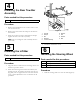
G018766
Figure5
1.Steeringwheelcap5.Steeringwheel
2.Bolt
6.Steeringshaftcover
3.Lockwasher
7.Steeringshaft
4.Largewasher
2.Slidethesteeringwheeldownontotheshaftandinstall
thelargewasher,lockwasher,andtightenwiththebolt.
Torquethesteeringwheelboltto25.4N-m(225in-lb).
3.Alignthesteeringwheelcapwiththesteeringwheel
pocketandlightlypressitintoposition.
7
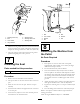
InstallingtheSeat
Partsneededforthisprocedure:
1
Seat
Procedure
1.Removethenutandwashersfromeachbolt.
2.Lineuptheboltsontheseatwiththeholesintheseat
pan.
3.Placetheseatontotheseatpan.Lifttheseatpan
carefully.
4.Installthelockwashersandtightenallfourofthenuts
totheseatpan.
5.Lowertheseat,adjustittothemostforwardposition
andinstalltheseatholddownbolt.
1
2
3
4
5
6
7
G018767
Figure6
1.Bolt5.Bolt
2.Lockwasher6.Washer
3.Washer7.Nut
4.Nut
8
RemovingtheMachinefrom
thePallet
NoPartsRequired
Procedure
1.Placepiecesofwoodoneachsideofthepallet,
approximately100–150mm(4to6inches)inheight
underbothtransportwheels.
2.Liftthemachineslowlywiththeliftbar.
3.Oncethemachineisfullyraised,removetheblock
fromthepalletatthedrawbarendandplaceitunder
thedrawbarskid.Thepalletcanbemovedawayfrom
thesteeringwheelendofthemachine.Carefullyroll
themachineoffofthewoodedsupportandontothe
ground.
4.Adjusttheliftingrodstoachievealeveldrawbarand
thentightentheM16nutstolocktheadjustment.
5.Tightenthewheellugnutstoatorqueof108N-m(80
ft-lbs).
6.Storetheliftingleverandsecureitwiththelynchpin.
RefertotheOperator’sManualandtheEngineManualfor
startingprocedures.
ChecktheengineRPMandadjustitto3200RPM.
4