
Operator's Manual


1
InstallingtheTransport
Wheels
Partsneededforthisprocedure:
2Transportwheel
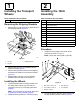
RemovingtheShippingBrackets
1.Removethelugnutssecuringthewheelhubsto
theshippingbracket(Figure3).
g279735
Figure3
1.Lugnut
3.Shippingbracket
2.Lagbolt
2.Removetheotherlugnutthreadedontothe
wheel-hubstud(Figure3).
3.Removethelagboltsthatsecuretheshipping
bracketstothepallet,andremovethebracket
(Figure3).
4.Repeatsteps1through3fortheshipping
bracketattheothersideofthemachine.
InstallingtheWheels
1.Looselyassemblethe2transportwheelsonto
thewheelhubswiththelugnutsthatyou
removedinRemovingtheShippingBrackets
(page8).
Note:Youwilltorquethelugnutsattheendof
2InstallingtheHitchAssembly(page8).
2.Adjustthetireairpressureto103kPa(15psi).
2
InstallingtheHitch
Assembly
Partsneededforthisprocedure:
1Lockbracket
4
Bolt(M10x30mm)
4
Lockwasher(M10)
6
Washer(M10)
4
Nut(M10)
1Hitchassembly
1
Bolt(M10x100mm)
1
Locknut(M10)
1
Bolt(M12x100mm)
2
Washer(M12)
1
Locknut(M12)
2
Spacerwasher(whenapplicable)
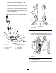
Procedure
1.Installthelockbrackettotheframeofthe
machineasshowninFigure4.
Note:Torquethenutsto52N∙m(38ft-lb).
g036890
Figure4
1.Bolt—M10x30mm(4)4.Nut—M10(4)
2.Lockwasher—M10(4)
5.Lockbracket
3.Washer—M10(4)
2.Securethehitchtothehitchpivotbracketwith
theappropriatehardware;refertoFigure5.
8