Operator’s Manual Form No. 3364-606 Rev A Register your product at www.Toro.com MH-400 Material Delivery Unit Model No. 44930--Serial No. 310000001 and Up Model No. 44931--Serial No. 310000001 and Up Model No. 44933--Serial No. 310000001 and Up Model No. 44934--Serial No. 310000001 and Up Model No. 44937 Model No.
Table of Contents Product Identification........................................................................................................1 Model Name and Serial Number ...............................................................................1 Purchase Date and Distributor Information ...............................................................1 Specifications ....................................................................................................................2 Introduction....
How to Install the Cross Conveyor.......................................................................... 19 How to Install the Swivel Kit .................................................................................... 19 How to Install the MH Processor ............................................................................. 20 How to Prepare the Electrical Connections on SH Model....................................... 20 How to Prepare the Electrical Connections on EH Model.....................
Belt and Rear Gate Seals ..............................................................................38 Options...........................................................................................................38 Safety Decals .................................................................................................38 Electric Brakes ...............................................................................................38 Maintaining the Electric Brakes .............................
Figure 15: Control Pendant For EH Models ............................................................ 24 Figure 16: Open rear gate / close rear gate, side view ........................................... 27 Figure 17: Raise the MH-400 to unload into a smaller machine ............................. 28 Figure 18: Positioning the Pendant Swing Arm....................................................... 28 Figure 19: Twin Spinner Disc Settings ....................................................................
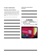
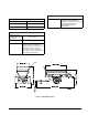
Product Identification Purchase Date and Distributor Information Model Name and Serial Number The MH-400 model number and serial number are located on a Model, Serial Number plate mounted on the left side of the front panel (Figures 1 and 2).When you contact an authorized Toro distributor for service or parts, give the distributor the model number and serial number, as well as the part numbers, description, and quantity of parts you require.
Specifications IMPORTANT: These specifications are subject to change without notice. They are provided for reference purposes only. Contact an authorized Toro distributor for up-to-date or additional information. Tires 82.5 x 40 x 40.25 cm – 10 ply (33 x 16 x 16.1 in) Size Maximum Inflation pressure Weights Base Model 1,360 kg (3,000 lb) GVWR 6,713 kg (14,800 lb) Payload 5,353 kg (11,800 lb) 172 kPa (25 psi) Hydraulic System Minimum flow 23 L/min (6 U.S.
Other Specifications Noise Electrical System Voltage 12 V Maximum Amperage draw 2.98 A Fuse 15 A Under normal operating conditions, the MH400 has an equivalent, continuous, A-weighted sound level of 82 dB(A), complying with Directive 98/37/EC and amendments. Other Specifications Maximum payload capacity to the top of the hopper 2.21 m3 (78 ft3) Maximum belt speed 2.9 rpm or 18 m (60 ft) per minute Vibration Under normal operating conditions, the MH-400 does not produce vibrations over 2.
Introduction Read this Operator’s Manual carefully before operating the MH-400 Material Delivery Unit. Keep it in an accessible location. To get a replacement manual, go to www.toro.com. This Operator’s Manual may also be available in other languages. Go to www.toro.com to download one. How to Use the Operator’s Manual Follow all safety precautions and operating recommendations to ensure safe and trouble-free operation of the MH-400.
About the MH-400 Material Delivery Unit The MH-400 Material Delivery Unit is a low-impact multi-purpose work trailer designed for the turf grass maintenance industry. • The triple-sealed rollers provide long-lasting high performance and require virtually no maintenance. • The bi-directional conveyor belt allows materials and supplies to be loaded into the MH-400, as well as unloaded. • The multi-position rear gate can be adjusted from a closed position up to 12.5 cm (5 in) open to pass material.
Hydraulic Power Pack Option Use this option to supply hydraulic pressure to the MH-400 and its equipment when the tow vehicle has only a PTO (power take-off unit). The power pack is a selfcontained pump and hydraulic reservoir that runs off the tow vehicle’s PTO. Another advantage is that the hydraulic power pack is better protected from contaminants than most tow vehicle hydraulic systems. Electric brakes may be legally required by some jurisdictions.
Safety Instructions Read this Operator’s Manual carefully. Follow all safety precautions and operating recommendations to ensure safe and trouble-free operation of the MH-400 Material Delivery Unit. WARNING: The MH-400 is equipped only for off-road use. Do not use it on public roads. Safe Operating Practices • Ensure that qualified personnel have made all recommended maintenance and adjustments to the MH-400 before use. Notify your supervisor about any adjustments made to the MH-400.
For best results, use a tow vehicle with at least 45 hp and four-wheel drive. A tow vehicle with less than 45 hp will limit where you can go and how much payload you can deliver. For example, a 27 hp tow vehicle can tow a fully loaded MH-400 over flat terrain, but not on steep hills. A four-wheel drive will also improve performance on hills. WARNING: Ensure that the tow vehicle has enough power and traction to pull a full load. If not, reduce the size of loads.
WARNING: Do not carry passengers in the hopper. Unloading Do not stand behind the MH-400 when unloading or spreading. The twin spinner, cross conveyor and processor eject particles and dust at a high speed. WARNING: Do not unload the MH-400 or disconnect it from the tow vehicle while on a hill. WARNING: Ensure that the MH-400 is connected to the tow vehicle before unloading. CAUTION: Always remove options before loading or unloading the MH-400 from a trailer.
Hills WARNING: Use extreme caution when traveling on hills, especially when turning. CAUTION: When disconnecting the MH-400, always block the wheels to prevent movement. See safety decals on page 12. Traveling across steep hills with the unit fully loaded could result in tipping over, or a loss of traction for the MH-400 or tow vehicle. Always travel straight up and down hills—do not travel sideways or diagonally.
that raising the MH-400 can increase the risk of tipping over. Figure 4: Rear jack leg positions for parking and traveling A. Support position – Lower the jack leg before disconnecting from the tow vehicle B. Travel position – Raise the jack leg before traveling. Remove the jack and store on the tongue C. Safety pin D. Rear jack leg E. 5 cm (2 in) maximum gap Figure 5: Tongue weight A. B. C. D. E.
MH-400. If problems result, this may violate local regulations, void the warranty, or cause injury or death. WARNING: Install the hydraulic cylinder supports before doing any maintenance work under the hopper (Figure 6). Safety Decals Important safety decals on your MH-400 indicate areas with potential safety hazards. Replace any decal that becomes lost, damaged, or illegible.
115-2047: Warning - Hot 119-6850: Shear hazard Locking bar up 93-9899: Crush hazard Install the cylinder lock when extended 93-9852: Warning – Lift Cylinder 119-6822: Floor Conveyer On - Off 119-6821: Do not travel with cross conveyor extended Always center cross conveyor when traveling 119-6830: Base Unit 119-6804: Thrown object hazard Stay a safe distance from the machine Setup Instructions Page 13
119-6836: Consult Operator’s Manual Locate weight so that rear of weight case is 28 in (71 cm) from front face of hitch tube 119-6832: Adjustments 119-6831: Use ISO VG-68 Hydraulic fluid 90 L (23.8 U.S.
119-6834: Consult Operator’s Manual Maximum load for optional caddy 1500 lb (680 kg) 119-6845: Tailgate Height Indicator Setup Instructions Page 15
119-6825: Safe range for traveling with options attached Consult Operator’s Manual Page 16 Setup Instructions
Setup Instructions 4. Slide the rear option attachment clamp assembly out of the quick-attach slots and into the brackets. An authorized Toro distributor normally sets up the MH400 Material Delivery Unit at the time of purchase. See the Setup Manual for more information. 5. Insert the front edge of the option up and under the rear of the MH-400 into the front clamps on the brackets. If you purchased the electric brakes, your authorized Toro distributor will install these too. 6.
Figure 7: Installing an option / removing an option A. B. C. D. E. F. Rear of MH-400 Option attachment bracket Lock pin Lock ring Safety latch clip Clamp handle How to Connect the Option’s Hydraulics WARNING: Ensure that the tow vehicle is turned off before making connections, to prevent the option from accidentally turning on. To connect the hydraulic hoses to the option control valve on the MH-400 fender: Page 18 G. H. I. J. K. L.
How to Install the Cross Conveyor How to Install the Swivel Kit The cross conveyor spreads material to either side of the MH-400 (Figure 8). The swivel kit allows the cross conveyor to swivel freely in a 270 degree arc, or to be locked into one of five fixed positions, 45 degrees apart (Figure 9). Figure 8: Cross conveyor, side view A. B. C. D. E.
How to Install the MH Processor How to Prepare the Electrical Connections on SH Model The MH Processor is used to screen a wide variety of material. There are three available electrical connections to be made with your MH-400 SH model: Option control valve reference Hose connections Quick-attach brackets MH Processor Hydraulic hoses 1. Using the hydraulic controls, raise the MH-400 so the quick attach brackets are aligned with the top of the hopper of the processor.
How to Prepare the Electrical Connections on EH Model There are three available electrical connections to be made with your MH-400 EH: 1. 2. • Electrical power from your tow-vehicle • Control Pendant • Electric Brakes (if equipped) Install the Tow-Vehicle electrical connection kit to the tow-vehicle’s battery, being careful to route the wires safely to avoid heat or abrasion damage. Connect the MH-400 EH electrical harness into the tow-vehicle’s plug.
Operating Instructions 8. Check the hydraulic oil level in the tow vehicles tank and add more to fill it, if necessary. (See the tow vehicle’s Owner’s Manual). Connecting the MH-400 to the Tow Vehicle 9. Test the hydraulics before operating the MH-400 for the first time. 1. Connect the MH-400 hitch to the tow vehicle using a 25 mm (1 in) diameter safety approved hitch pin and safety clip (not supplied). IMPORTANT: Use a high-strength hitch pin that is approved for tow vehicle hitches. 2.
How to Disconnect the MH-400 from the Tow Vehicle 1. Park the tow vehicle and the MH-400 on dry, level ground. 2. Set the parking brake on the tow vehicle, shut off the engine, and remove the key. 3. Place blocks under the front and back of the wheels. 4. Relieve the pressure from the hydraulic system. 5. Disconnect the hydraulic hoses and the electrical connection from the tow vehicle. Coil and store them on the front of the MH-400. 6.
Figure 14: Hydraulic control valves A. B. C. D. Conveyor belt direction (left control valve) Raise and lower MH-400 (center control valve) Options on and off (right control valve) Option hydraulic quick connectors Operating the Hydraulic Controls and Options on EH Models WARNING: Before operating the MH-400, read and understand the entire Operator’s Manual and all safety decals.
Reduce option speed Belt start Increase option speed Belt stop All Stop WARNING: Do not leave the MH-400 unattended while it is running. Reduce belt speed Increase belt speed Turn on the control pendant by rotating the “all stop” button clockwise until it pops up. Conveyor Belt • To unload the MH-400, press the “belt start” button on the control pendant. This moves material to the rear along the conveyor belt. • To stop the conveyor belt, press the “belt stop” button on the control pendant.
Option Control • To turn on the option, press the “option start” button on the control pendant. • To turn off the option, press the “option stop” button on the control pendant. WARNING: Do not leave the option running while unattended. IMPORTANT: Do not press the “option start” button on the control pendant without an option connected. This can damage the hydraulics on the MH-400.
Bulk Unloading Loading Material 1. Back the MH-400 into the location where you want the material deposited. 2. Release the rear gate latches and turn on the conveyor belt. 3. If desired, raise the rear of the MH-400. This unloads material at a different angle, and allows quick unloading of the entire load. Load the MH-400 from the top or from the rear. For most materials, such as sand or gravel, you can use a front-end bucket loader.
Unloading Into Smaller Machines 1. 2. Raise the rear of the MH-400 high enough to accommodate the smaller machine underneath (Figure 16). Follow the procedure for bulk unloading or controlled unloading. Operating the Pendant Swing Arm on EH Models The pendant swing arm holds the control pendant when mounted on the MH-400. The following procedure should be used for operating the swing arm. 1.
Always test new materials by spreading them in an open area away from people. 8. 4. Start the tow vehicle and turn on the tow vehicle hydraulics. 5. On the SH model turn on the on/off pendant switch to start spreading. On the EH model turn on the option then the conveyer belt with the control pendant Note – When driving over uneven terrain, raise the MH400 to the maximum safe traveling range.
Application Application Spinner Factor Speed Floor Control Rear Gate Base Setting Disc Application Spread Setting Width Ultra Light 1 10 Maximum 25mm (1”) 1 A 12.2m (40’) Light 3 10 Maximum 76mm (3”) 1 B 12.2m (40’) Medium 5 4 Maximum 76mm (3”) 2 B 6.7m (22’) Medium Heavy 10 3 Maximum 76mm (3”) 3 B 3.4m (11’) Heavy 17 3 Maximum 127mm (5”) 3 B 3.
Disc Settings A B Figure 19: Twin Spinner Disc Settings Base Settings 1 2 3 Figure 20: Twin Spinner Base Settings Operating Instructions Page 31
How to Operate the Cross Conveyor How to Spread Material from the Cross Conveyor How to Extend and Retract the Cross Conveyor 1. Turn off the tow vehicle. Always operate the cross conveyor separately from the main conveyor belt. 2. On SH models using the control levers, turn on the option and the conveyor belt (unload position). CAUTION: Always return the cross conveyor to the center position when traveling, otherwise the cross conveyor can hit people or objects, and can also be damaged (Figure 21).
How to Operate the Swivel Kit To direct the flow of material from the cross conveyor in any direction, pull up the spring-loaded locking pin on the swivel kit into the unlock or open position. This allows you to manually move the cross conveyor freely from side to side on the swivel bearing (Figure 22). To keep the cross conveyor in a fixed position, release the spring-loaded locking pin into one of the five locking positions on the swivel kit.
How to Operate the Option Caddy (1) 4. The option caddy is designed for one person to lift, transport, and mount the cross conveyor, swivel kit and processor onto the MH-400 (Figure 24). It can also be used to store the cross conveyor. WARNING: Always transport options on the option caddy in the lowest possible position and on level ground. 5. Transport the option to the rear of the MH-400 and raise it into position for mounting. 6.
How to Operate the Option Caddy (2) 10. Position the fork height and roll the caddy forward until the forks are completely through the option (Figure 28). Figure 26: Option Caddy The option caddy is designed for one person to lift, transport, and mount the Twin Spinner, swivel kit, or cross conveyor onto the MH-400 (Figure 26). WARNING: The option caddy’s maximum carrying load is 227 kg (500 lb). Do not carry people on it. 8. Position the caddy against the rear of the option. 9.
3. If the MH-400 is operating properly, engage the hydraulics by switching on the tow vehicle PTO. WARNING: Always disengage the PTO when the MH-400 is not in use. WARNING: Do not adjust the relief valve, or your warranty may be voided. It is set to factory specifications. Electric Brakes Figure 29: Cross conveyor storage stands How to Operate the Hydraulic Power Pack WARNING: Keep clear of all moving parts. 1. Engage the tow vehicle’s PTO. Do not exceed the maximum speed of 540 rpm. 2.
Maintenance Instructions Rely on an authorized Toro distributor to help you use and maintain the MH-400 for best performance. Tires and Wheels The recommended tire pressure is 172 kPa (25 psi), or as recommended by the tire manufacturer. Check for excessive wear or visible damage. WARNING: Disconnect all power sources to the MH-400 before doing maintenance work. Check that the wheel bolts are tightened to 13.8 kg-m (100 ft-lb) and that none are missing.
Belt and Rear Gate Seals 6. Rotate the star wheel in the opposite direction until the wheel turns freely with a slight drag on the lining. 7. Replace the adjusting hole cover. 8. Repeat the above procedure on each brake. Check all rubber seals for wear or damage. Replace or repair the seals if any leakage occurs. Options Check that the quick-attach brackets are securely locked into place and that the safety clips are installed. Replace missing safety clips.
CAUTION: Take precautions when servicing brakes: • Do not create or breathe dust. • Do not machine, file, or grind the brake linings. • Do not use compressed air or dry brushing for cleaning.
2. Go to the front on the same side, loosen the locking nut, and tighten the adjuster nut by one quarter turn. 3. Tighten both locking nuts before running the MH-400. 4. Load the MH-400 with material and run the load through until empty. Repeat multiple times. 5. Stop the belt and go to the rear of the machine to observe the results. Note – The belt may move slightly depending on the type of load and its position. If the belt is not touching the side rails, you do not need to track the belt.
How to Tension the Conveyor Belt How to Adjust the Conveyor Drive Chain 1. Park the MH-400 on level ground with the rear gate and feed gate at least 6.25 mm (¼ in) off the floor (depending on the material). If the conveyor drive chain is loose, it needs to be tightened (Figure 32). 2. Fully load the machine with sand that you expect the MH-400 to use. 3. 1. Turn off the tow vehicle and set the parking brake. 2. Remove the rear conveyor drive guard.
Grease and Lubrication Schedule • Clean grease fitting of foreign matter. Figure 33 shows the grease point locations. • Pump grease into all bearings and bushings. • Use an automotive all-purpose grease. • Clean off excess grease. • A spray or brush-on lubricant may be used on the conveyer drive chain instead of grease. • Clean and repack wheel bearings every year or 300 hours. • Lubricate regularly, after 25 hours of normal operation.
Material Properties: Viscosity, ASTM D445: cSt @ 40° C 52 to 62 cSt @ 100° C 79.1 to 9.8 Viscosity Index: ASTM D2270: PourPoint, ASTM D97: 140 to 152 -35° F to -46° F Industry Specifications: API GL-4, Powerfluid 821 XL, Ford New Holland FNHA-2-C-201.00, Kubota UDT, John Deere J20C, Vickers 35VQ25 and Volvo WB101/BM NOTE: Many hydraulic fluids are almost colorless, making it difficult to spot leaks. A red dye additive for the hydraulic system oil is available in 2/3 oz (20 ml) bottles.
Hydraulic Schematic For SH Model Figure 34: Hydraulic schematic For SH Model 1. 2. 3. 4. 5. 6. 7. 8. 9. 10. 11. 12. 13. 14. 15. 16. 17. 18. 19. 20. 21. 22.
Hydraulic Schematic For EH Model Figure 35: Hydraulic schematic For EH Model 1. 2. 3. 4. 5. 6. 7. 8. 9.
Electrical Schematic For SH Model Figure 36: Electrical schematic For SH Model 1. 2. 3. 4. 5. 6. 7. 8. 9.
Electrical Schematic For EH Model Figure 37: Electrical schematic For EH Model 1. 2. 3. 4. 5. 6. 7. 8. 9. 10. 11. 12. 13.
How to Wash the MH-400 Long-term Storage of the MH-400 Salts, road tar, tree sap, fertilizers, and chemicals may damage the painted finish of the MH-400. Wash off these deposits as soon as possible with detergent and water. Additional cleaners or solvents may be needed, but ensure that they are safe for painted surfaces. Before storing the MH-400 for the season: 1. Thoroughly clean the MH-400. Remove parts if required. 2. Remove the control pendant on the EH models. 1.
Troubleshooting General Troubleshooting If the problem still occurs after all the checks listed below have been completed, contact an authorized Toro distributor for service. Symptom Cause The belt control valve is in the center position. The belt is incorrectly tensioned. The material is too densely packed or clumped together (open rear gate latches to bulk unload). The on/off pendant switch is in the ‘floor off’ position for SH models.
Brake Troubleshooting Low Voltage or Amperage Most brake malfunctions that cannot be corrected by synchronization or by normal brake adjustments can usually be traced to electrical system failure. The most common electrical problem for the brakes is low or no voltage or amperage. This is usually caused by: Mechanical causes should be obvious, such as bent or broken parts, worn linings or magnets, seized lever arms or shoes, scored drums, or loose parts.
Symptom Locking brakes Intermittent brakes Harsh brakes Noisy brakes Surging brakes Dragging brakes Troubleshooting Cause Improper brake adjustment Improper synchronization Faulty controller Loose, bent, or broken brake components Out-of-round brake drums (distorted shape) Faulty controller Broken wires Loose connections Faulty ground Under adjustment Improper synchronization Faulty controller Under adjustment Lack of lubrication Broken brake components Incorrect brake components Oil or grease on ma
MH-400 Maintenance Record Service Performed Page 52 Date Notes Troubleshooting
Troubleshooting Page 53