
Operator's Manual


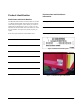

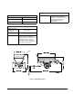

Table of Contents Page iii
Belt and Rear Gate Seals ..............................................................................38
Options...........................................................................................................38
Safety Decals.................................................................................................38
Electric Brakes ...............................................................................................38
Maintaining the Electric Brakes ...............................................................................38
How to Adjust the Electric Brakes..................................................................38
Brake Shoes and Linings...............................................................................38
Yearly Brake Cleaning and Inspection...........................................................38
Lubrication......................................................................................................39
Magnets .........................................................................................................39
How to Measure Brake Voltage .....................................................................39
How to Measure Brake Amperage.................................................................39
How to Track the Conveyor Belt..............................................................................39
How to Tension the Conveyor Belt ..........................................................................41
How to Adjust the Conveyor Drive Chain ................................................................41
Grease and Lubrication Schedule ...........................................................................42
Hydraulic Fluid System ............................................................................................42
Hydraulic Schematic For SH Model.........................................................................44
Hydraulic Schematic For EH Model.........................................................................45
Electrical Schematic For SH Model .........................................................................46
Electrical Schematic For EH Model .........................................................................47
How to Wash the MH-400........................................................................................48
Long-term Storage of the MH-400...........................................................................48
How to Transport the MH-400 .................................................................................48
Troubleshooting ..............................................................................................................49
General Troubleshooting .........................................................................................49
Brake Troubleshooting.............................................................................................50
Electrical Troubleshooting..............................................................................50
Low Voltage or Amperage .............................................................................50
Short Circuits..................................................................................................50
Brake Troubleshooting Table.........................................................................50
MH-400 Maintenance Record..................................................................................52
Warranty ...................................................................................................Back Cover
Figures
Figure 1: Model Serial Number plate.........................................................................1
Figure 2: Identification plate information....................................................................1
Figure 3: MH-400 dimensions....................................................................................3
Figure 4: Rear jack leg positions for parking and traveling .....................................11
Figure 5: Tongue weight..........................................................................................11
Figure 6: Hydraulic cylinder support in place...........................................................12
Figure 7: Installing an option / removing an option..................................................18
Figure 8: Cross conveyor, side view........................................................................19
Figure 9: Swivel kit, side view..................................................................................19
Figure 10: MH Processor, side view........................................................................20
Figure 11: Control Pendant on Swing Arm..............................................................21
Figure 12: Control Pendant on Tow Vehicle Mount.................................................21
Figure 13: Connect hydraulic hoses to tow vehicle .................................................22
Figure 14: Hydraulic control valves..........................................................................24