
Setup Instructions


Page ii Table of Contents
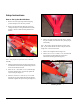
Figure 13: Remove lift fork stop plates......................................................................5
Figure 14: Install forks onto the slide plate................................................................5
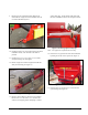
Figure 15: Twin Spinner handle openings.................................................................6
Figure 16: Install Twin Spinner handles....................................................................6
Figure 17: Hopper front guard...................................................................................6
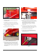
Figure 18: Install hopper front guard.........................................................................7
Figure 19: Twin Spinner option, side view ................................................................ 7
Figure 20: Install bolts and tighten set screws ..........................................................8
Figure 21: Cross conveyor storage stands ...............................................................8
Figure 22: Cross conveyer handles .......................................................................... 8
Figure 23: MH Processor in shipping crate...............................................................9
Figure 24: Processor stand ....................................................................................... 9
Figure 25: Install hydraulic power pack...................................................................10
Figure 26: Remove hydraulic valve cover and hydraulic guard .............................11
Figure 27: Re-install fender guard with hydraulic valve bank .................................11
Figure 28: Remove hydraulic line clamps and hardware........................................12
Figure 29: Remove and discard far hydraulic hose ................................................12
Figure30: Remove hydraulic fittings........................................................................12
Figure 31 Install connector fitting to inside valve port.............................................12
Figure 32: Install tee fitting to outer valve port ........................................................13
Figure 33: Re-install hose to side of tee fitting........................................................13
Figure 34: Install end of Item 8 hose to open hard line...........................................13
Figure 35: Re-install hydraulic line clamps.............................................................. 13
Figure 36: Install Item 6 hose and fitting end to point B......................................... 14
Figure 37: Install Item 7 hose and fitting ends to point A and B..............................14
Figure 38: Remove hydraulic hose clamp...............................................................14
Figure 39: Space and attach grey wiring harness...................................................14
Figure 40: Slide sheath to hydraulic hose attachment; attach hydraulic hoses...... 15
Figure 41: Pull hoses straight and tighten...............................................................15
Figure 42: Attach mounting bracket for electric socket..........................................15
Figure 43: Wiring Schematic For On/Off Pendant Switch On SH Models ..............17
Figure 44: Hydraulic Assembly For On/Off Pendant Switch On SH Models...........18
Figure 45: Attach SH Battery Harness to Solenoid Harness ..................................19
Figure 46: Plug Details............................................................................................19
Figure 47: Attach SH Battery Harness to Solenoid Harness ..................................19
Figure 48: EH Control Pendant Mount.................................................................... 20
Figure 49: EH Control Pendant Mount.................................................................... 20
Figure 50: EH Control Pendant Mount Backing Plate.............................................20
Figure 51: Brake shoe assemblies, left side/right side............................................21
Figure 52: Install brake kit .......................................................................................22
Figure 53: Raise and support the MH-400..............................................................23
Figure 54: MH-400 with tires raised in air ...............................................................23
Figure 55: Flip tire and axle assemblies on end......................................................23
Figure 56: Remove hub assembly ..........................................................................24
Figure 57: Mount hub assembly onto drum.............................................................24
Figure 58: Install dust cover onto axle ....................................................................24
Figure 59: Adjust wheel bearings............................................................................25
Figure 60: Prepare 2-prong plug.............................................................................25
Figure 61: Install plug mounting bracket on front....................................................26
Figure 62: Run wires for left side up and under pivot point of MH-400...................26
Figure 63: Run wire along hydraulic hoses to 7-prong plug...................................27
Figure 64: Brake controller (example).....................................................................30
Figure 65: Install brake controller on tow vehicle....................................................30