
Operator's Manual


MediaandAdditionalParts
Description
Qty.
Use
Operator'sManual
1
Readthemanualbeforeoperatingthemachine.
DeclarationofConformity
1
TheDeclarationofConformityservesasEUproofof
certication.
Attachmentclamps2Usetomountattachments.
Note:Determinetheleftandrightsidesofthe
machinefromthenormaloperatingposition.
1
InstallingtheHitch
Partsneededforthisprocedure:
2
Bolt(1x6-1/2inches)
2
Locknut(1inch)
Procedure
1.Locateandremovetheloosepartsboxshipped
onthefender.
2.Removetherearsupportlegfromtheshipping
positionandplaceitinthedownposition.
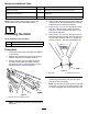
3.Removethehitchfromtheshippingposition
bycuttingbothstrapssecuringthehitchto
thefender(Figure3).Removebothmounting
bracketsfromthefenderanddiscard.
g014065
Figure3
1.Removehitchfromshippingposition
Note:2peoplearerequiredtoremovethehitch
assembly.
4.Slidethehitchtubetongueintoplaceatthefront
ofthemachine.Ensurethatthejackmounting
bracketfacesouttowardstheleftside.
5.Placeabolt(1x6–1/2inch)throughtheframe
andhitchtubeandsecureitwithalocknut
(Figure4).Torquethelocknutto976to1,193
N-m(720to880ft-lb).
6.Placeabolt(1x6–1/2inch)throughthetopof
theframeanddownthroughthehitchtubeand
secureitwithalocknut(Figure4).Torquethe
locknutto976to1,193N-m(720to880ft-lb).
g014066
Figure4
1.Hitchtube2.Mountingboltandnut
7.Removethejackassemblyfromtherearleg.
Installthejackassemblyontothehitchtube,
placingthepinhorizontally.
Note:Donotplacethepinthroughthetophole
ofthejack,oryouwillnotbeabletoremovethe
pinwhentheweightcaseissecuredtothehitch.
10