Form No. 3449-177 Rev A Operator's Manual QuickGroom 710 Model No. 46405AA—Serial No. 321000001 and Up Model No. 46405BA—Serial No. 321000001 and Up Register at www.Toro.com/bullseye.
WARNING Model No. CALIFORNIA Proposition 65 Warning Use of this product may cause exposure to chemicals known to the State of California to cause cancer, birth defects, or other reproductive harm. Serial No. This manual identifies potential hazards and has safety messages identified by the safety-alert symbol (Figure 2), which signals a hazard that may cause serious injury or death if you do not follow the recommended precautions.
Safety and Instructional Decals Safety General Safety Safety decals and instructions are easily visible to the operator and are located near any area of potential danger. Replace any decal that is damaged or missing. This product is capable of causing personal injury. Always follow all safety instructions to avoid serious personal injury. • Read and understand the contents of both this Operator’s Manual and the operator’s manual of the traction unit before using this machine.
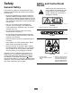
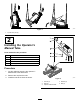
Setup 1. Place the pallet on level ground. 2. Attach lifting cables to the crossbar and pallet. 1 Removing the Machine from the Pallet No Parts Required Procedure The machine is shipped vertically on the pallet. Use the following instructions to remove it from the pallet. DANGER The attachment is unstable and could swing when lifted, injuring anyone beneath it or around it. • Refer to the lifting machine operator’s manual to ensure that it is rated to lift the attachment.
g367256 Figure 4 1. 3-point hitch pins (3) 2 Installing the Operator’s Manual Tube Parts needed for this procedure: 1 Operator’s Manual tube 2 Plate 2 Bolt (M8) 2 Washer 2 Locknut (M8) Procedure 1. Cut the cable ties securing the Operator’s Manual tube to the attachment. 2. Remove the cap from the tube. 3. Install the tube to the frame as shown. g367289 Figure 5 1. Locknut (2) 4. Washer (2) 2. Plate (2) 5. Bolt (2) 3.
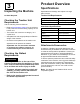
Product Overview 3 Specifications Inspecting the Machine Specifications and design are subject to change without notice.
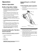
Connecting to a 3-Point Hitch Operation Before Operation Connecting the Lower Link Arms Before Operation Safety • Never allow children or untrained people to operate or service the machine. Local regulations may restrict the age of the operator. The owner is responsible for training all operators and mechanics. 1. Ensure that the attachment is positioned on a level surface. 2. Remove the hairpin cotters and hitch pins from the attachment.
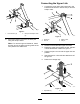
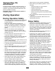
Connecting the Upper Link 1. Connect the upper link to the lower hole in the bracket frame secure it with the link pin and the hairpin cotter. g345394 Figure 7 1. Lower link arm (2) 2. Hitch pin and hairpin cotter (2) g345396 Figure 8 6. Secure the lower link arms to the hitch pins using the hairpin cotters. Note: For maximum ground clearance, install the hitch pins in the lower mounting holes of the hitch plate for the attachment. 1. Upper link 3. Hairpin cotter 2. Jam nut 4. Link pin 2.
Transporting the Attachment • Never leave a running machine unattended. • Before leaving the operating position, do the To begin transport operation, raise the machine. To avoid loss of control, traverse steep inclines slowly, approach rough areas at reduced speed and cross severe undulations carefully. Important: Do not exceed transport speeds of 12 km/h (7.5 mph).
Operating Tips or the edge caves in. Establish a safety area between the machine and any hazard. • Make very gradual turns. Never make sharp turns • Identify hazards at the base of the slope. If with the attachment. there are hazards, mow the slope with a power walk-behind mower. • Do not use the attachment if the ground is too wet.
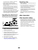
Removing the Attachment 1. Park the machine on a level surface, engage the parking brake, shut off the engine, and remove the key from the traction unit. 2. Lower the 4 storage legs. Important: Ensure that the attachment does not slide off the traction unit and cannot roll away. g345394 Figure 13 1. Lower link arm (2) g346767 2. Hitch pin and hairpin cotter (2) Figure 11 1. Lynch pin 2. Storage leg 3. Lower the attachment to the ground. 4. Secure the attachment from movement. 5.
Storage Storage Safety • Before adjusting, cleaning, storing, or repairing the machine, park the it on a level surface; engage the parking brake of the traction unit; shut off the engine; remove the key; and wait for all movement to stop before leaving the traction unit. • Store the machine on the storage stands positioned on a firm, level surface so that it does not sink or tip over. • Store the machine away from areas of human activity. • Do not allow children to play on or around the stored machine.
Troubleshooting Problem The attachment loosened too little material. The appearance of the field is poor. Possible Cause Corrective Action 1. The working depth is set too shallow. 1. Increase the working depth. 2. The infill material is too compacted. 2. Drive multiple passes over the turf, each with a deeper setting. 1. The working depth is set too deep. 1. Decrease the working depth. 2. The drag brush does not drag over the ground. 2.
Notes:
California Proposition 65 Warning Information What is this warning? You may see a product for sale that has a warning label like the following: WARNING: Cancer and Reproductive Harm—www.p65Warnings.ca.gov. What is Prop 65? Prop 65 applies to any company operating in California, selling products in California, or manufacturing products that may be sold in or brought into California.
Warranty Statement One-Year Limited Warranty Conditions and Products Covered Parts Your Bullseye product (“Product”) is warranted to be free from defects in materials or workmanship for 1 year. Where a warrantable condition exists, we will repair the Product at no cost to you including diagnostics, labor, parts, and transportation. This warranty begins on the date the Product is delivered to the original retail purchaser.