Form No. 3449-180 Rev A Towable Electric Lift Kit QuickGroom 710 Model No. 46407 Installation Instructions Important: This kit is not compatible with the Wing Kit. Installation Loose Parts Use the chart below to verify that all parts have been shipped.
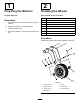
1 2 Preparing the Machine Installing the Wheels No Parts Required Parts needed for this procedure: Procedure 1 Wheel frame assembly 2 Bolt (M10 x 25) 2 Spring washer 1. Park the traction unit and attachment on a level surface. 2 Washer (M10) 2. Engage the traction unit parking brake. 4 Bushing 3. Lower the attachment. 2 Wheel 4. Shut off the traction-unit engine and remove the key. 2 Wheel shaft 2 Wheel shaft pin Procedure Install the 2 wheels to the frame assembly as shown.
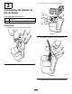
2. 3 Pull the cover up and remove the plug. Connecting the Switch to the Actuator Parts needed for this procedure: 1 Switch box 1 Actuator Procedure 1. Remove the Torx screw from the actuator. g367359 Figure 3 3. Plug in the connector from the switch box. g367361 Figure 2 g367360 Figure 4 4. 3 Lower the cover and secure it with the screw.
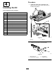
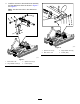
Procedure 4 1. Installing the Kit Install the wheel frame assembly to the attachment and secure both ends using a bushing and roll pin. Parts needed for this procedure: 2 Bushing 2 Roll pin 1 Long spacer 1 Bolt (M12 x 55) 2 Bolt (M12 x 100) 2 Washer (M12) 4 Large washer (M12) 2 Locknut (M12) 2 Spacer (25 mm) 2 Spacer (21 mm) 1 Link pin 1 Hairpin cotter 1 Tow bar 1 Adjustment handle 1 Top link g350085 Figure 5 1. Bushing 2. 2.
3. Install the actuator to the wheel frame assembly and the attachment frame as shown in Figure 7 and Figure 8. Note: Use the lower hole in the attachment frame. g367308 Figure 8 g367307 Figure 7 1. Bolt—M12 x 100 3. Spacer—25 mm (2) 2. Large washer—M12 (2) 4. Locknut (M12) 5 1. Spacer—21 mm (2) 3. Large washer—M12 (2) 2. Bolt—M12 x 100 4.
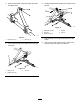
4. Remove the hairpin cotters and hitch pins from the attachment. 6. Install the adjustment handle to the center of the top link. g350120 Figure 11 1. Adjustment handle 4. Top link 2. Hitch pin 5. Link pin 3. Hairpin cotter (2) g345395 Figure 9 1. Hairpin cotter (3) 5. Secure the tow bar to the attachment using the hitch pins. g350119 Figure 10 1. Hitch pin (2) 7. Use the hitch pins to secure the top link to the frame. 8.
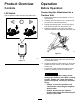
Product Overview Operation Controls Before Operation Lift Switch Connecting the Attachment to a Traction Unit Use the switch to raise and lower the attachment. 1. Position the attachment and traction unit on a level surface. 2. Carefully drive the traction unit in reverse until the tow bar is near the attachment. 3. Engage the parking brake, shut off the engine, and remove the key from the traction unit. 4.
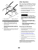
After Operation Disconnecting the Battery Clamps Important: Disconnect the battery clamps after operation. 1. Park the machine on a level surface. 2. Engage the parking brake, shut off the engine, and remove the key from the traction unit. 3. Disconnect the negative (black clamp) cable from the traction unit battery. 4. Disconnect the positive (red clamp) cable from the traction unit battery. WARNING Incorrect battery cable routing could damage the machine and cables, causing sparks.