Form No. 3443-901 Rev B Operator's Manual FieldSweep 660 Model No. 46412—Serial No. 321000001 and Up Register at www.Toro.com/bullseye.
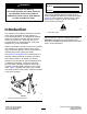
WARNING Model No. CALIFORNIA Proposition 65 Warning Use of this product may cause exposure to chemicals known to the State of California to cause cancer, birth defects, or other reproductive harm. Serial No. This manual identifies potential hazards and has safety messages identified by the safety-alert symbol (Figure 2), which signals a hazard that may cause serious injury or death if you do not follow the recommended precautions. Introduction g000502 Figure 2 1.
Contents Safety Safety ....................................................................... 3 General Safety ................................................... 3 Safety and Instructional Decals .......................... 4 Setup ........................................................................ 5 1 Removing the Machine from the Pallet............................................................... 5 2 Inspecting the Machine .................................... 6 Product Overview .................
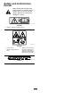
Safety and Instructional Decals Safety decals and instructions are easily visible to the operator and are located near any area of potential danger. Replace any decal that is damaged or missing. decal105-0698 105-0698 1. Warning—read the Operator’s Manual. decal144-7905 144-7905 1. Thrown object hazard—keep bystanders away. 2. Warning—remove the key, secure the machine from movement, and read the Operator’s Manual before performing maintenance.
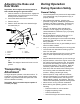
Setup 1 1. Place the pallet on level ground. 2. Remove the debris bins; refer to Emptying the Debris Bins (page 12). 3. Attach lifting cables to the middle of the crossbar and upper 3-point hitch pins. Removing the Machine from the Pallet No Parts Required Procedure The machine is shipped vertically on the pallet. Use the following instructions to remove it from the pallet. DANGER The attachment is unstable and could swing when lifted, injuring anyone beneath it or around it.
g349013 Figure 4 1. 3-point hitch pins (3) Checking the Ballast Requirements 2 WARNING Inspecting the Machine Mounting the machine to the rear of the traction unit decreases the weight on its front axle. No Parts Required Failure to add required ballast may result in an accident and severe injury or death. Checking the Traction Unit Requirements • To ensure adequate steering control and stability you may need to add ballast to the front of the traction unit.
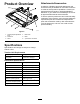
Attachments/Accessories Product Overview A selection of Bullseye approved attachments and accessories may be available for use with the machine to enhance and expand its capabilities. Contact your Authorized Service Dealer or authorized Bullseye distributor or go to www.Toro.com/Bullseye for a list of all approved attachments and accessories. To ensure optimum performance and continued safety certification of the machine, use only genuine Bullseye replacement parts and accessories.
Connecting to a 3-Point Hitch Operation Before Operation Connecting the Lower Link Arms Before Operation Safety • Never allow children or untrained people to operate or service the machine. Local regulations may restrict the age of the operator. The owner is responsible for training all operators and mechanics. 1. Ensure that the attachment is positioned on a level surface for installation. 2. Remove the hairpin cotters and hitch pins from the attachment.
5. Secure the right and left lower link arms to the frame using the hitch pins. 4. Tighten the jam nut to secure the upper link into position. 5. Start the traction unit and lift the attachment off the ground. Adjusting the Working Depth Important: Do not adjust the working depth so that it would damage the ground surface. 1. Park the machine on a level surface, engage the parking brake, shut off the engine, and remove the key from the traction unit. 2. Secure the attachment from movement. 3.
Adjusting the Rake and Rear Brush During Operation During Operation Safety Important: Do not adjust the working depth so that it would damage the ground surface. 1. General Safety Park the machine on a level surface, engage the parking brake, shut off the engine, and remove the key from the traction unit. 2. Secure the attachment from movement. 3. Remove the pin. 4. Raise or lower the rake to the desired height and install the pin.
attachment while operating on slopes can cause the machine to become unstable. – Wait for all moving parts to stop before leaving the machine. • Do not operate the machine when there is the risk • Use extreme caution with other attachments. of lightning. These can change the stability of the machine and cause a loss of control. Always keep the machine in gear when going down slopes. Do not coast downhill (applicable only to gear-drive units).
After Operation 4. Remove and empty the debris bins. After Operation Safety • Park the tow vehicle on a level surface; engage the parking brake of the tow vehicle; shut off the engine; remove the key; and wait for all movement to stop before leaving the operator’s position. • Allow the machine to cool before storing the machine in any enclosure. • Keep all parts of the machine in good working condition and all hardware tightened. g349107 • Replace all worn, damaged, or missing decals. Figure 12 1.
Removing the Attachment 1. Park the machine on a level surface, engage the parking brake, shut off the engine, and remove the key from the traction unit. 2. Lower the attachment to the ground. 3. Secure the attachment from movement. 4. Loosen the upper link jam nut and rotate the upper link. 6. Remove the lower link arms. Important: Ensure that the attachment does not slide off the traction unit and cannot roll away. g349059 Figure 15 g349060 Figure 14 1. Upper link 3. Hairpin cotter 2.
Maintenance CAUTION If you leave the key in the switch, someone could accidently start the engine and seriously injure you or bystanders. Remove the key from the traction unit switch before you perform any maintenance. Recommended Maintenance Schedule(s) Maintenance Service Interval Maintenance Procedure After the first 20 hours • Check the roller bearings and driveline; replace worn components. Every 100 hours or yearly, whichever comes first • • • • Grease the attachment.
Greasing the Attachment Adjusting the Guard Plate Service Interval: Every 100 hours or yearly, whichever comes first Adjust the guard plate to change the material flow across the sieve. Lower the guard plate to allow more infill material to fall onto the field. The attachment has grease fittings that you must lubricate regularly with No. 2 lithium grease. Also, lubricate the attachment immediately after every washing and after long periods without use. 1.
Changing the Vibration Sieve 1. 2. 3. 4. 5. Park the machine on a level surface. Engage the parking brake, shut off the engine, and remove the key from the towing vehicle. Secure the attachment from movement. Remove the debris bins as described in Emptying the Debris Bins (page 12). Loosen the bolts for the lock plates 1 turn. 10. Lower the side plates and tighten the bolts.. 11. Tighten the bolts. 12. Rotate the lock plates and tighten the bolts. 13.
6. Lower the pulley to increase the tension on the chain until the chain is tight. Storage 7. Tighten the bolt. 8. Install the chain cover as shown in Figure 23. Storage Safety • Before adjusting, cleaning, storing, or repairing the machine, park the it on a level surface; engage the parking brake of the traction unit; shut off the engine; remove the key; and wait for all movement to stop before leaving the traction unit.
Troubleshooting Problem Possible Cause Corrective Action 1. The working depth is too deep. 1. Decrease the working depth 2. The vibrating sieve is clogged. 3. The field is too wet. 4. The mesh of the vibrating sieve is too small. 2. Clean the vibrating sieve. 3. Wait for the field to dry. 4. Use a sieve with a larger mesh. 1. The working depth is too shallow. 1. Increase the working depth. 2. The mesh of the jigging sieve is too large. 3. A brush is worn. 2. Use a sieve with a smaller mesh. 1.
California Proposition 65 Warning Information What is this warning? You may see a product for sale that has a warning label like the following: WARNING: Cancer and Reproductive Harm—www.p65Warnings.ca.gov. What is Prop 65? Prop 65 applies to any company operating in California, selling products in California, or manufacturing products that may be sold in or brought into California.
Warranty Statement One-Year Limited Warranty Conditions and Products Covered Parts Your Bullseye product (“Product”) is warranted to be free from defects in materials or workmanship for 1 year. Where a warrantable condition exists, we will repair the Product at no cost to you including diagnostics, labor, parts, and transportation. This warranty begins on the date the Product is delivered to the original retail purchaser.