Form No. 3449-141 Rev B Operator's Manual FieldFill 660 Model No. 46423—Serial No. 321000001 and Up Register at www.Toro.com/bullseye.
WARNING Model No. CALIFORNIA Proposition 65 Warning Use of this product may cause exposure to chemicals known to the State of California to cause cancer, birth defects, or other reproductive harm. Serial No. This manual identifies potential hazards and has safety messages identified by the safety-alert symbol (Figure 2), which signals a hazard that may cause serious injury or death if you do not follow the recommended precautions. Introduction g000502 Figure 2 1.
Contents Safety Safety ....................................................................... 3 General Safety ................................................... 3 Safety and Instructional Decals .......................... 4 Setup ........................................................................ 5 Removing the Machine from the Pallet ................ 5 Installing the Front Caster Wheel ........................ 5 Inspecting the Machine....................................... 6 Product Overview ....
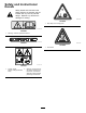
Safety and Instructional Decals Safety decals and instructions are easily visible to the operator and are located near any area of potential danger. Replace any decal that is damaged or missing. decal144-8878 144-8878 1. Stay away from moving parts decal105-0698 105-0698 1. Warning—read the Operator’s Manual. decal133-8061 133-8061 decal144-8880 144-8880 1. Hot surface decal144-7905 144-7905 1. Thrown object hazard—keep bystanders away. 2.
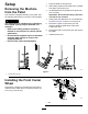
Setup Removing the Machine from the Pallet 1. Place the pallet on level ground. 2. Attach lifting cables to the middle of the crossbar and upper 3-point hitch pins. 3. Lift the attachment and pallet off the ground 50 mm (2 inches). Important: Ensure that the lifting cable does not slide on the crossbar. The machine is shipped vertically on the pallet. Use the following instructions to remove it from the pallet.
Inspecting the Machine Product Overview Checking the Traction Unit Requirements Use the following list as a reference: • Refer to Specifications (page 7) for the minimum horse power and minimum lifting capacity for the traction unit. • The traction unit must have a category I 3-point hitch. • Adequate front-end weight (ballast) to offset the weight of the machine. • Check the tire air pressure of the traction unit. g346706 Figure 5 Adjust the tire air pressure as needed.
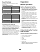
Specifications Operation Specifications and design are subject to change without notice. Before Operation Traction Unit Requirements Lifting capacity 200 kg (441 lb) Before Operation Safety Minimum output-power rating 7.45 Kw (10 HP) • Never allow children or untrained people to Minimum hydraulic flow rate 10 L/minute (2.6 US gallons/minute) Minimum hydraulic pressure 70 bar (1015 psi) Tow system 3-point hitch, category 1 operate or service the machine.
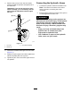
Connecting the Attachment to a Traction Unit 6. Insert the right and left lower link arms onto the hitch pins. Connecting to a 3-Point Hitch Connecting the Lower Link Arms 1. Ensure that the attachment is positioned on a level surface. 2. Remove the lynch pins from the hitch pins. g345655 Figure 7 1. Lower link arm (2) 7. g345654 Figure 6 1. Hairpin cotter (2) 3. Linkage arm (2) 2. Hitch pin (2) 3.
Connecting the Chain or Upper Link Arm 3. Note: Connect the attachment using the chain for Pull the chain tight to the upper bracket and slide a link into the bracket slot. a more consistent working depth. It also allows the user to adjust the working depth prior to connecting it to a traction unit. If you are connecting the chain, continue as follows: 1. If the front wheel assembly is not installed, install it.
3. Connecting the Hydraulic Hoses Remove the lynch pin from the front caster wheel and slide the spacers and spindle out of the caster arm. 1. Connect the hydraulic hoses to the traction unit. Note: The return line contains a non-return Important: If you do not remove the front valve to prevent connecting the hoses incorrectly. wheel assembly, you could damage the turf while using the attachment with the upper link arm. 2.
Adjusting the Caster Wheels Transporting the Attachment Adjust the caster wheels to change the height of the attachment. Use higher settings for grooming and lower settings for decompacting. To begin transport operation, raise the machine. To avoid loss of control, traverse steep inclines slowly, approach rough areas at reduced speed and cross severe undulations carefully.
During Operation • Do not operate the machine when there is the risk • During Operation Safety of lightning. Use Bullseye accessories, attachments, and replacement parts only. • The owner/operator can prevent and is responsible • • • • • • • • • • • • • • • Slope Safety for accidents that may cause personal injury or property damage. Wear appropriate clothing, including eye protection; long pants; substantial, slip-resistant footwear; and hearing protection.
Operating Tips cause a loss of control. Always keep the machine in gear when going down slopes. Do not coast downhill (applicable only to gear-drive units). • Make very gradual turns. Never make sharp turns with the attachment. • Do not use the attachment if the ground is too wet. Operating the Attachment • Look backward frequently to ensure that the Important: Do not exceed 8 km/h (5.0 mph) while machine is operating properly, and alignment is maintained with previous passes.
After Operation 3. If an upper link arm is connected, loosen the jam nut and rotate the upper link. After Operation Safety • Park the traction unit on a level surface; engage the parking brake of the traction unit; shut off the engine; remove the key; and wait for all movement to stop before leaving the operator’s position. • Allow the machine to cool before storing the machine in any enclosure. • Keep all parts of the machine in good working condition and all hardware tightened.
6. Remove both lower link arms. Important: Ensure that the attachment does not slide off the traction unit and cannot roll away. g345655 Figure 17 1. Lower link arm 2. Hitch pin and lynch pin 7. Start the traction unit and drive it away from the attachment. 8. Install the lynch pins to the hitch pins. g345654 Figure 18 1. Hairpin cotter (2) 3. Linkage arm (2) 2.
Maintenance Recommended Maintenance Schedule(s) Maintenance Service Interval Before each use or daily Maintenance Procedure • Check the hydraulic lines for leaks, loose fittings, kinked lines, loose mounting supports, wear, weather, and chemical deterioration. Every 15 hours • Tension the chain. Every 50 hours • Grease the attachment. CAUTION If you leave the key in the switch, someone could accidently start the engine and seriously injure you or other bystanders.
5. Move the frame away from the deck. 6. Remove the 2 nuts securing the cover and remove the cover. g347904 Figure 21 Caster wheel bearings g347881 Figure 20 1. Nut (2) 2. Cover Reverse the procedure to install the cover and frame. Greasing the Attachment Service Interval: Every 50 hours The attachment has grease fittings that you must lubricate regularly with No. 2 lithium grease. Also, lubricate the attachment immediately after every washing and after long periods without use.
Service Interval: Every 15 hours Checking the Hydraulic Lines Important: If the chain breaks or is removed for Service Interval: Before each use or daily Tensioning the Chain service, manually calibrate the timing of the brush positions; otherwise, the brushes may interfere with each other during operation and damage the attachment. Refer to the Service Manual for information. 1. Park the machine on a level surface. 2.
Storage Storage Safety • Before adjusting, cleaning, storing, or repairing the machine, park the it on a level surface; engage the parking brake of the traction unit; shut off the engine; remove the key; and wait for all movement to stop before leaving the traction unit. • Store the machine on the storage stands positioned on a firm, level surface so that it does not sink or tip over. • Store the machine away from areas of human activity. • Do not allow children to play on or around the stored machine.
Notes:
Notes:
Notes:
California Proposition 65 Warning Information What is this warning? You may see a product for sale that has a warning label like the following: WARNING: Cancer and Reproductive Harm—www.p65Warnings.ca.gov. What is Prop 65? Prop 65 applies to any company operating in California, selling products in California, or manufacturing products that may be sold in or brought into California.
Warranty Statement One-Year Limited Warranty Conditions and Products Covered Parts Your Bullseye product (“Product”) is warranted to be free from defects in materials or workmanship for 1 year. Where a warrantable condition exists, we will repair the Product at no cost to you including diagnostics, labor, parts, and transportation. This warranty begins on the date the Product is delivered to the original retail purchaser.