Form No. 3443-913 Rev A Operator's Manual FieldClean 580 Model No. 46425—Serial No. 321000001 and Up Register at www.Toro.com/bullseye.
WARNING Model No. CALIFORNIA Proposition 65 Warning Use of this product may cause exposure to chemicals known to the State of California to cause cancer, birth defects, or other reproductive harm. Serial No. This manual identifies potential hazards and has safety messages identified by the safety-alert symbol (Figure 2), which signals a hazard that may cause serious injury or death if you do not follow the recommended precautions. Introduction g000502 Figure 2 1.
Safety Emptying the Waste Receptacle ....................... 19 Emptying the Dust Bag ..................................... 20 Removing the Attachment ................................ 20 Maintenance ........................................................... 23 Recommended Maintenance Schedule(s) ........... 23 Maintenance Safety.......................................... 23 Greasing the Attachment .................................. 24 Servicing the PTO.............................................
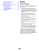
Safety and Instructional Decals Safety decals and instructions are easily visible to the operator and are located near any area of potential danger. Replace any decal that is damaged or missing. decal144-7911 144-7911 1. Cutting hazard of hand—close and lock the cover. decal105-0698 decal144-8256 105-0698 144-8256 1. Warning—read the Operator’s Manual. 1. PTO—350 to 540 rpm decal133-8061 133-8061 decal144-7905 144-7905 1. Thrown object hazard—keep bystanders away. 2.
decal144-8339 144-8339 1. Entanglement hazard—keep away from moving parts. 2. Warning—read the Operator’s Manual. decal144-8369 144-8369 1.
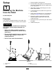
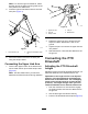
Setup 1. Place the pallet on level ground. 2. Ensure that the rake section is turned upward and cannot be damaged when the attachment is put on the ground. 3. Attach lifting cables to the lifting eyes on both sides of the machine. Removing the Machine from the Pallet 4. Lift the attachment and pallet off the ground 50 mm (2 inches). 5. Gently lower the attachment in a controlled way as shown in Figure 3 until it is on the ground. No Parts Required 6.
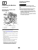
Checking the Ballast Requirements 2 WARNING Inspecting the Machine Mounting the machine to the rear of the traction unit decreases the weight on its front axle. No Parts Required Failure to add required ballast may result in an accident and severe injury or death. Checking the Traction Unit Requirements • To ensure adequate steering control and stability you may need to add ballast to the front of the traction unit. • Refer to the traction unit operator's manual for ballast requirements.
Attachments/Accessories Product Overview A selection of Bullseye approved attachments and accessories may be available for use with the machine to enhance and expand its capabilities. Contact your Authorized Service Dealer or authorized Bullseye distributor or go to www.Toro.com/Bullseye for a list of all approved attachments and accessories. To ensure optimum performance and continued safety certification of the machine, use only genuine Bullseye replacement parts and accessories.
Understanding the Traction Unit Controls Operation Before Operation Familiarize yourself with the operation of the following traction unit controls before operating the machine: Before Operation Safety • PTO engagement • 3 point hitch (raise/lower) • Never allow children or untrained people to • Clutch operate or service the machine. Local regulations may restrict the age of the operator. The owner is responsible for training all operators and mechanics.
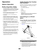
Note: For maximum ground clearance, install the hitch pins in the lower mounting holes of the hitch plate for the attachment. 5. Insert the right and left lower link arms onto the hitch pins (Figure 7). g345539 Figure 8 g345538 1. Upper link arm 4. Link pin 2. Jam nut 3. Hairpin cotter 5. Slotted hole 2. Grease the threaded steel upper link arm tubes. 3. Rotate the upper link arm to shorten the link. Adjust it until the attachment is flat on the ground. 4.
g347461 Figure 9 4. Assemble the outer PTO driveshaft section to the traction-unit PTO output shaft (Figure 10). Note: Pull on the driveshaft to ensure that the locking pin engages the PTO output shaft. g347524 Figure 11 1. 76 mm (3 inches) g007328 Figure 10 3. Traction-unit PTO output shaft 2. Attachment gearbox 1. PTO output shaft (traction unit) 3. PTO driveshaft 7. 2. PTO shaft coupler 5. Note: Ensure the same amount is removed from each section.
11. Hold the driveshaft sections parallel to each other and check to ensure that they overlap 150 mm (6 inches) or more (Figure 14). Note: If the sections do not overlap 150 mm (6 inches), contact your authorized distributor. g347459 Figure 14 1. Attachment gearbox 3. Shafts furthest apart 2. Traction-unit PTO output shaft g347524 Figure 12 12. 1. Cut the driveshaft section. 8. Important: Do not use the attachment if the PTO driveshaft is damaged; replace the damaged driveshaft before operation.
Installing the PTO Driveshaft Important: Refer to the PTO driveshaft owner’s manual for additional operating and safety information. CAUTION Operating the machine without the PTO guards and shields may cause injury or death. Keep all PTO guards and shields in place. g345541 Figure 16 Important: When connecting the PTO, ensure that the attachment is not lifted higher than necessary. Lifting the attachment too high causes the PTO driveshaft knuckles to break (Figure 15).
5. Adjusting the Working Depth of the Brush Verify that the telescoping tube has a minimum of 150 mm (6 inches) overlap when the attachment is raised to the maximum height. Important: Do not adjust the working depth so that it would damage the subsoil. 1. Park the machine on a level surface, engage the parking brake, shut off the engine, and remove the key from the traction unit. 2. Secure the attachment from movement. 3. On each side of the attachment, loosen the 2 bolts a few turns.
Using the Inspection Hatch Adjusting the Working Depth of the Rake 1. Open the latches on both sides of the attachment. Important: Do not adjust the working depth so that it would damage the ground surface. 1. Park the machine on a level surface, engage the parking brake, shut off the engine, and remove the key from the traction unit. 2. Secure the attachment from movement. 3. On each side of the attachment, loosen the 2 bolts a few turns. Note: Use the tools supplied in the toolbox.
Adjusting the Vacuum Suction Force Adjusting the Angle of the Sieve If the receptacle retains too much material that should have been sieved, angle the sieve to give the material more time to fall through the sieve. 1. Park the machine on a level surface, engage the parking brake, shut off the engine, and remove the key from the traction unit. 2. Secure the attachment from movement. 3. Open the inspection hatch. 4. Loosen the nuts on both sides of the attachment 1 turn. 1.
Practicing the Operating Procedures • Before using the attachment, find a clear area and practice operating the traction unit with the attachment installed. • Important: If there are sprinkler heads, electrical or communication lines, or other obstructions in the area being aerated, mark these locations to ensure that these items are not damaged during operation.
• • • • If possible, keep the attachment lowered to the damage some parts if not performed with special tools by trained technicians. Do not operate the attachment if the PTO or driveshaft guards are missing. Be careful when turning the machine so that the traction unit tires do not contact the PTO driveshaft. Secure hydraulic hoses, electrical wiring, ropes, and other items to keep them from contacting the PTO driveshaft guard. ground while operating on slopes.
4. If desired, mount the upper link arm in the slotted hole so that the attachment follows the terrain; refer to Connecting the Upper Link Arm (page 10). 5. Raise the attachment and drive to the location where you will use the attachment. Emptying the Waste Receptacle Important: Do not exceed 12 km/h (7.5 mph) while transporting the attachment. 6. Lower the attachment until it is approximately 50 mm (2 inches) above the ground. 7. Engage the PTO at a low rpm. 8.
Emptying the Dust Bag CAUTION 7. Hang the bag loops on the hooks. 8. Install the bag over the hose opening. 9. Tighten the band. Inhaling dust is hazardous to your health. 10. Wear a dust mask when emptying the dust bag. Removing the Attachment Close the door for the vacuum box and secure it. 1. Park the machine on a level surface, engage the parking brake, shut off the engine, and remove the key from the traction unit. 1.
6. Remove the PTO driveshaft from the attachment. 8. Loosen the upper link jam nut and rotate the upper link. g345541 Figure 30 4. Bolt 1. Gearbox input shaft 2. Nut 3. PTO shaft coupler 7. g346444 Figure 32 5. PTO driveshaft Remove the PTO driveshaft from the traction unit. 1. Upper link arm 3. Hairpin cotter 2. Jam nut 4. Link pin 9. Remove the upper link arms. 10. Remove the lower link arms.
12. Install the hairpin cotters to the hitch pins. g345540 Figure 34 1. Hairpin cotter (3) 2. Hitch pin (3) Important: When storing the attachment, do not allow the brush to touch the ground or other objects to avoid bending the bristles.
Maintenance Recommended Maintenance Schedule(s) Maintenance Service Interval Maintenance Procedure After the first 20 hours • Grease the attachment. • Check the belt tension. Every 100 hours Yearly • • • • • Grease the attachment. Check the brushes for wear. Repair or replace as necessary. Check the gearbox for leaks. Check the gearbox fluid level; add SAE 90 gearbox oil as needed. Check the belt tension and wear. • Service the PTO.
Greasing the Attachment Servicing the PTO Service Interval: After the first 20 hours Service Interval: Yearly Every 100 hours The attachment has grease fittings that you must lubricate regularly with No. 2 lithium grease. Also, lubricate the attachment immediately after every washing and after long periods without use. 1. Park the machine on a level surface, engage the parking brake, shut off the engine, and remove the key from the traction unit. 2. Secure the attachment from movement. 3.
4. Adjusting the Belt Tension Verify that the belt deflects 2 mm (0.08 inch) when pulled with 4.5 kg (9.9 lb) of force at mid-span. Depending on the intensity of operation, wear on the driveline can cause the V-belts to slip. Tighten the V-belts when this occurs. 1. Park the machine on a level surface, engage the parking brake, shut off the engine, and remove the key from the traction unit. 2. Secure the attachment from movement. 3. Remove the nuts and side panel. g345201 Figure 38 5.
6. Adjust the bolt to increase or decrease the pressure of the pulley on the belt. Changing the Sieve 7. Verify that the belt deflects 2 mm (0.08 inch) when pulled with 4.5 kg (9.9 lb) of force at mid-span. Continue adjusting the tension as needed. Optional meshes are available and may be needed for processing different types of material. 1. Park the machine on a level surface, engage the parking brake, shut off the engine, and remove the key from the traction unit. 2.
Troubleshooting Problem The waste receptacle collects too much material. The attachment does not clean enough material. The appearance of the field is poor. There are squeaking noises during operation. Possible Cause Corrective Action 1. The PTO speed is too high. 1. Lower the PTO speed. 2. 3. 4. 5. 6. 7. 2. 3. 4. 5. 6. 7. The jigging sieve is too flat. The working depth is too deep. The jigging sieve is clogged. The driving speed is too slow. The field is too wet.
Notes:
Notes:
Notes:
California Proposition 65 Warning Information What is this warning? You may see a product for sale that has a warning label like the following: WARNING: Cancer and Reproductive Harm—www.p65Warnings.ca.gov. What is Prop 65? Prop 65 applies to any company operating in California, selling products in California, or manufacturing products that may be sold in or brought into California.
Warranty Statement One-Year Limited Warranty Conditions and Products Covered Parts Your Bullseye product (“Product”) is warranted to be free from defects in materials or workmanship for 1 year. Where a warrantable condition exists, we will repair the Product at no cost to you including diagnostics, labor, parts, and transportation. This warranty begins on the date the Product is delivered to the original retail purchaser.