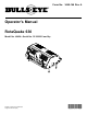
Form No. 3449-146 Rev A Operator's Manual RotaQuake 630 Model No. 46454—Serial No. 321000001 and Up Register at www.Toro.com/bullseye.
WARNING CALIFORNIA Proposition 65 Warning Use of this product may cause exposure to chemicals known to the State of California to cause cancer, birth defects, or other reproductive harm. Introduction g347059 Figure 1 This attachment aerates and decompacts soil. It is intended to be used by professional, hired operators in commercial applications. It is designed primarily for working large areas on well-maintained lawns in parks, golf courses, sports fields, and on commercial grounds.
Safety Specifications .................................................... 9 Before Operation ................................................. 10 Before Operation Safety ................................... 10 Understanding the Traction Unit Controls ........................................................ 10 Connecting to a 3-Point Hitch............................ 10 Connecting the PTO Driveshaft ........................ 12 Adjusting the Operating Depth ..........................
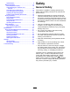
Safety and Instructional Decals Safety decals and instructions are easily visible to the operator and are located near any area of potential danger. Replace any decal that is damaged or missing. decal105-0698 105-0698 1. Warning—read the Operator’s Manual. decal133-8061 133-8061 decal144-8338 144-8338 1. Entanglement hazard—keep away from moving parts.. decal144-7905 144-7905 1. Thrown object hazard—keep bystanders away. 2.
decal144-8339 144-8339 1. Entanglement hazard—keep away from moving parts. 2. Warning—read the Operator’s Manual.
Setup 1 Removing the Attachment from the Pallet No Parts Required Procedure The attachment is shipped vertically on the pallet. Perform the following instructions to remove it from the pallet. DANGER The attachment is unstable and could swing when lifted, injuring anyone beneath it or around it. • Refer to the lifting machine operator’s manual to ensure that it is rated to lift the attachment. • Ensure the lift height is kept to a minimum and only high enough to remove the shipping material.
2 Installing the Knives and Gearbox Breather No Parts Required Procedure 1. Install the attachment to a traction unit; refer to Connecting to a 3-Point Hitch (page 10) and Connecting the PTO Driveshaft (page 12). 2. Raise the attachment off the ground. 3. Perform the following steps to shut off the traction unit: A. Ensure that the traction unit is parked on a level surface. B. Engage the parking brake. C. Shut off the traction unit and remove the key. 4.
3 Inspecting the Machine No Parts Required Checking the Traction Unit Requirements g349218 Figure 5 1. Breather 11. 2. Gearbox Close the hatch and secure it with the previously removed hardware. g007332 Figure 6 3-Point Hitch and PTO Components 1. Lower link arm 2. Upper link arm 3. PTO driveshaft 4. Sway link Use the following list as a reference: • Refer to the specifications section for the recommended horse power and the minimum lifting capacity for the traction unit; Specifications (page 9).
Checking the Ballast Requirements Product Overview Specifications WARNING Traction Unit Requirements Mounting the machine to the rear of the traction unit decreases the weight on its front axle. Failure to add required ballast may result in an accident and severe injury or death. • To ensure adequate steering control and stability, you may need to add ballast to the front of the traction unit.
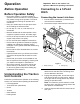
Operation Important: Refer to the traction unit Operator's Manual for operating instructions. Before Operation Connecting to a 3-Point Hitch Before Operation Safety • Never allow children or untrained people to Connecting the Lower Link Arms operate or service the machine. Local regulations may restrict the age of the operator. The owner is responsible for training all operators and mechanics. • Keep your hands clear of the joint pivot areas 1.
g347650 Figure 9 1. Upper link arm 3. Hairpin cotter 2. Jam nut 4. Link pin g347649 Figure 8 1. Lower link arm (2) 6. 2. Hitch pin and hairpin cotter (2) Secure the lower link arms to the hitch pins using the hairpin cotters. Connecting the Upper Link Arm 1. Connect the upper link arm to the bracket and secure it with the link pin and the hairpin cotter (Figure 9). 2. Grease the threaded steel upper link arm tubes. 3. Rotate the upper link arm to tighten or loosen the link as needed. 4.
Connecting the PTO Driveshaft Adjusting the PTO Driveshaft Length Adjust the length of the PTO driveshaft whenever you install the attachment to a different traction unit. Important: If the length of PTO is not adjusted properly, using the attachment can damage the traction unit or the attachment. The overlapping length of the cylinders must be at least 150 mm (6 inches). The length changes when you lift or install the attachment on a different traction unit. 1.
g347459 Figure 15 9. g347524 Figure 13 1. 76 mm (3 inches) Remove and cut each section at the mark (Figure 14). Note: Ensure the same amount is removed from each section. g347473 Figure 14 1. Cut the driveshaft section. 8. 10. Raise the attachment to the position where the traction-unit PTO output shaft and gearbox input shaft are furthest apart (Figure 16). 11. Hold the driveshaft sections parallel to each other and check to ensure that they overlap 150 mm (6 inches) or more (Figure 16).
Installing the PTO Driveshaft Important: Refer to the PTO driveshaft owner’s manual for additional operating and safety information. CAUTION Operating the machine without the PTO guards and shields may cause injury or death. Keep all PTO guards and shields in place. Important: When connecting the PTO, ensure that the attachment is not lifted higher than necessary. Lifting the attachment too high causes the PTO driveshaft knuckles to break (Figure 17).
5. Verify that the telescoping tube has a minimum of 150 mm (6 inches) overlap when the attachment is raised to the maximum height. g345541 Figure 18 1. Gearbox input shaft 4. Bolt 2. Nut 3. PTO shaft coupler 5. PTO driveshaft 2. Assemble the PTO driveshaft to the PTO output shaft of the traction unit. g345507 Figure 20 Adjusting the Operating Depth g007328 Figure 19 1. PTO output shaft (traction unit) 3. PTO driveshaft 2. PTO shaft coupler 3.
Practicing the Operating Procedures Before using the attachment, find a clear area and practice operating the traction unit with the attachment installed. Important: If there are sprinkler heads, electrical or communication lines, or other obstructions in the area being aerated, mark these locations to ensure that these items are not damaged during operation.
• • • • • • • • • • • • • • • • • • causes distractions; otherwise, injury or property damage may occur. Do not operate the machine when tired, ill, or under the influence of alcohol or drugs. Never carry passengers on the machine and keep bystanders and pets away from the machine during operation. Operate the machine only in good visibility to avoid holes or hidden hazards.
Operating the Attachment • If possible, keep the attachment lowered to the ground while operating on slopes. Raising the attachment while operating on slopes can cause the machine to become unstable. • Use extreme caution with other attachments. These can change the stability of the machine and cause a loss of control. Always keep the machine in gear when going down slopes. Do not coast downhill (applicable only to gear-drive units). 1.
• Keep all parts of the machine in good working condition and all hardware tightened. • Replace all worn, damaged, or missing decals. Removing the Attachment 1. Park the machine on a level surface with the attachment in the raised position, engage the parking brake, shut off the engine, and remove the key from the traction unit. 2. Lower the attachment stands (Figure 23). g007328 Figure 25 1. PTO output shaft (traction unit) 3. PTO driveshaft 2. PTO shaft coupler 6.
g347649 g347648 Figure 27 1. Lower link arm (2) Figure 28 2. Hitch pin and hairpin cotter (2) 9. Start the traction unit and drive it away from the attachment. 10. Install the hairpin cotters to the hitch pins (Figure 28). 1. Hairpin cotter (3) 20 2.
Maintenance Recommended Maintenance Schedule(s) Maintenance Service Interval Before each use or daily Maintenance Procedure • • • • Check the gearbox oil level. Grease the PTO shaft. Wash the attachment. Check for loose fasteners and tighten them as necessary. Every 50 hours • Check the gearbox for oil leakage. Every 100 hours • Check the condition of the knives. • Check the sowing elements for dirt and/or damage. • Check the sowing pipes and/or funnels. Yearly • Service the PTO.
Checking the Gearbox Oil Level Service Interval: Before each use or daily Every 50 hours Gearbox-oil specification: SAE 90 1. 2. Open the hatch; refer to Opening the Hatch (page 21). g007309 Figure 31 Check the oil level in the gearbox. The gearbox oil level should be at or above the gauge centerline (Figure 30). 8. Grease the cylinders. 9. Assemble the PTO and mount it on the attachment.
Storage Storage Safety • Before adjusting, cleaning, storing, or repairing the attachment, park the it on a level surface; engage the parking brake of the traction unit; shut off the engine; remove the key; and wait for all movement to stop before leaving the traction unit. • Store the attachment on the storage stands positioned on a firm, level surface so that it does not sink or tip over. • Store the attachment away from areas of human activity.
Troubleshooting Problem Too much damage to the soil to be treated. Possible Cause Corrective Action 1. Knives are damaged. 1. Try aligning the knives by straightening them using a hammer and anvil. 2. Knives are crooked. 3. Attachment is not in line with the tractor. 4. Not driven in a straight line. 5. Soil is too wet. 2. Align the knives. Mount new ones. 3. Adjust the attachment to align the knives with the tractor. 4. Try driving in a straight line. 5. Postpone the job until the soil has dried. 1.
Notes:
Notes:
Warranty Statement One-Year Limited Warranty Conditions and Products Covered Parts Your Bullseye product (“Product”) is warranted to be free from defects in materials or workmanship for 1 year. Where a warrantable condition exists, we will repair the Product at no cost to you including diagnostics, labor, parts, and transportation. This warranty begins on the date the Product is delivered to the original retail purchaser.
California Proposition 65 Warning Information What is this warning? You may see a product for sale that has a warning label like the following: WARNING: Cancer and Reproductive Harm—www.p65Warnings.ca.gov. What is Prop 65? Prop 65 applies to any company operating in California, selling products in California, or manufacturing products that may be sold in or brought into California.