
Operator's Manual


17
Maintenance
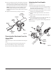
7. Remove the spark arrester.
8. Replace the old spark arrester with the new one.
9. Reassemble the mufer by reinstalling the plates and
tightening the three screws [torque to 7 in.lb (0.79 Nm)
minimum, 13 in.lb. (1.46 Nm) maximum].
10. Reassemble the mufer and mufer cover and attach to
the mufer gasket with the two screws.
11. Reinsert the mufer assembly and tighten two screws to en-
gine [torque to 60 in.lb (6.78 Nm) minimum, 80 in.lb. (9.04
Nm) maximum].
12. Reinstall the cover on the tool and fasten with the ve screws
[torque to 16 in.lb. (1.81 Nm) minimum,
22 in.lb.
(2.49 Nm)
maximum].
Note: Do not overtighten screws.
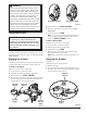
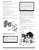
Replacing the Spark Plug
See Figure 10.
All item numbers included in this manual use a Champion
RCJ4, RCJ6Y or equivalent spark plug. Use a recommended
or equivalent replacement and replace annually.
1. Remove the spark plug boot.
2. Loosen the spark plug by turning it counterclockwise
with a socket.
3. Remove the spark plug.
4. Inspect the new spark plug. The spark plug must
be properly gapped and free of deposits in order to
ensure proper engine operation. The correct gap is
approximately 0.025 in. (0.64 mm). To widen gap, if
necessary, carefully bend the ground (top) electrode.
To lessen gap, gently tap ground electrode on a hard
surface.
5. Hand thread the new spark plug, turning it clockwise.
6. Tighten with a socket. [torque to 177 in.lb. (20 Nm)
minimum, 221 in.lb. (24.97 Nm) maximum. Do not
overtighten].
Figure 10
Spark
Plug
Spark Plug Boot
NOTICE:
Be careful not to cross-thread the spark plug. Cross-
threading will seriously damage the product.
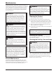
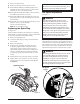
Idle Speed Adjustment
See Figure 11.
WARNING:
The blade/cutting head will move when
adjusting the idle speed. Wear all protective
clothing and keep all bystanders, children,
and pets at least 50 ft (15 m) away. Make
adjustments with the unit supported by hand
so that the blade/cutting head does not contact
the ground or any object. Keep all parts of your
body away from the blade/cutting head and
mufer. Failure to follow these instructions
could result in serious personal injury.
If the cutting attachment turns at idle, the idle speed screw
needs adjusting on the engine. Turn the idle speed screw
counterclockwise to reduce the idle RPM and stop the cut-
ting attachment movement. If the cutting attachment still
moves at idle speed, contact a qualied service dealer for
adjustment and discontinue use until the repair is made.
WARNING:
The cutting attachment should never turn at idle.
Turn the idle speed screw counterclockwise
to reduce the idle RPM and stop the cutting
attachment, or contact a service dealer for
adjustment and discontinue use until the repair
is made. Serious personal injury can result from
the cutting attachment turning at idle.
Figure 11
Idle Speed
Screw