
Operator's Manual

12
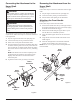
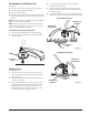
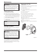
Connecting the Attachment to the
Upper Shaft
See Figure 2.
WARNING:
Never install, remove, or adjust any attachment
while power head is running. Failure to stop the
engine can cause serious personal injury. Never
operate power head without an attachment.
WARNING:
%HFHUWDLQWKHNQRELVIXOO\WLJKWHQHGEHIRUH
operating equipment; check it periodically for
tightness during use to avoid serious personal
injury.
7KHDWWDFKPHQWFRQQHFWVWRWKHSRZHUKHDGE\PHDQVRID
coupler device. Follow these steps to connect the attachment
to the upper shaft.
1. Stop the engine and disconnect the spark plug wire.
2. /RRVHQWKHNQREE\WXUQLQJLWFRXQWHUFORFNZLVH
3. Remove the end cap from the attachment shaft.
4. 3XVKLQWKHEXWWRQORFDWHGRQWKHDWWDFKPHQWVKDIW$OLJQ
WKHEXWWRQZLWKWKHJXLGHUHFHVVRQWKHSRZHUKHDGFRX-
pler and slide the two shafts together. Rotate the attach-
PHQW VKDIW XQWLO WKH EXWWRQ ORFNV LQWR WKH SRVLWLRQLQJ
hole.
Note: ,IWKHEXWWRQGRHVQRWUHOHDVHFRPSOHWHO\LQWKH
positioning hole, the shafts are not locked into place.
6OLJKWO\URWDWHIURPVLGHWRVLGHXQWLOWKHEXWWRQLV
locked into place.
5. 7LJKWHQWKHNQREVHFXUHO\E\WXUQLQJLWFORFNZLVH
Removing the Attachment from the
Upper Shaft
See Figure 2.
Follow these steps to remove the attachment from the upper
shaft.
1. Stop the engine and disconnect the spark plug wire.
2. /RRVHQWKHNQREE\WXUQLQJLWFRXQWHUFORFNZLVH
3. 3XVKWKHEXWWRQZKLOHSXOOLQJRXWWKHDWWDFKPHQW
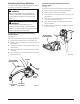
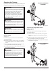
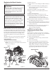
Attaching the Front Handle
See Figure 3.
Follow these steps to attach the front handle.
1. Press the front handle onto the top of the upper shaft, in
WKHSRVLWLRQLQGLFDWHGE\WKHDUURZRQWKHVKDIWDQJOLQJ
the handle toward the throttle trigger.
2. Place the front handle along the upper shaft to a posi-
WLRQWKDWDOORZVIRUFRPIRUWDEOHRSHUDWLRQ
3. ,QVHUWWKHKDQGOHVXSSRUWWDELQWRWKHVORWLQWKHIURQW
handle.
4. Align the hole in the front handle with the hole in the
handle support.
5. ,QVHUWEROWWKURXJKKROHVLQIURQWKDQGOHDQGKDQGOH
support. Secure handle in place using wing nut.
Note:'RQRWFRYHUDQ\SRUWLRQRIWKHZDUQLQJODEHOZLWK
the front handle.
Assembly
Figure 3
Bolt
Slot
Front
Handle
Throttle
Trigger
Handle
Support
Wing
nut
Knob
Figure 2
Button
Attachment
Shaft
Guide
Recess
Power
Head Shaft
Coupler
Tab