
Service Manual

GOVERNOR
5-2
GOVERNOR GEAR INSPECTION
1.
Inspect governor gear for worn and damage.
Replace
as
an unit, if wear and damage
ex-
ceed.
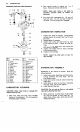
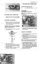
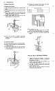
GOVERNOR REASSEMBLY
1.
Install thrust washer
(C)
and stuff into new
governor ass'y
(E)
to short stationary shaft
(A) until inner flange
(D)
fitted into groove
(B)
of the shaft
as
shown.
CAUTION: The
sleeve
can not
be
installed after
stuffed into the gear to the shaft.
Do
not reuse
governor
ass'y
once removed.
2.
After installed, governor ass'y should rotate
freely on the shaft.
3.
I
nstall governor gear cover.
4.
Place
a
new gasket on crankcase cover and put
small amount of grease around oil
seal
lips.
5.
Lubricate crankshaft bearing in crankcase
cover with engine oil.
6.
Suitably
set
the gear to be meshed with cam
gear when installing crankcase cover.
Reassembly
is
the reverse of removal. Note the
following points:
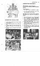
1.
Install governor lever (A) on governor shaft
(B)
and tighten nut
(C)
finger tight.
2.
The throttle and choke linkages can not
be
installed on the carburetor after the intake
pipe was installed.
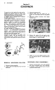
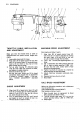
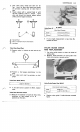
LINKAGE ADJUSTMENT
1.
Place throttle lever on dash in "FAST"
posi-
tion. (Equipment side)
2.
Loosen nut
(1),
that holds governor arm to
governor shaft
(2).
3.
Turn governor shaft
(2)
clockwise to the end of
travel by inserting needle
(3)
to shaft end hole
and tighten nut
(1).
NOTE: The throttle lever on
the
dash must
be
in
"FAST" position when adjusting the governor.
4.
Lower and raise throttle lever after adjustment
to be sure linkage
is
not binding.
5.
More throttle lever (on dash) up to "FAST"
position. Speed control lever
(C)
should be
in
wide open throttle position [aligned hole
(B)
and
(D)],
but not enough to move choke link
(4).
If adjustment
is
necessary, loosen cable
clamp bolt (A) and adjust cable.
6.
Retighten clamp bolt (A).