
Operator's Manual


7.Removethescrews(5mmand6mm)from
themuferprotector,andremovethemufer
protector(Figure46).
8.Removethescrews(4mm)fromthespark
arrester,andremovethesparkarresterfromthe
mufer(Figure46).
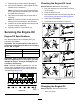
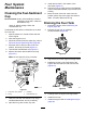
9.Useabrushtocarefullyremovecarbondeposits
fromthespark-arresterscreen(Figure47).
Note:Replacethesparkarresterifithas
breaksorholes.
g208746
Figure47
1.Screen
2.Brush
10.Installthesparkarrester,muferprotector,
exhaustdeector,andmuferinthereverse
orderofdisassembly.
11.Installthedividerplate(ifequipped);referto
InstallingtheDividerPlate(page28).
RemovingandInstalling
theEngine
RemovingtheEngine
WARNING
Thespringisundertensionwheninstalled
andcancausepersonalinjury.
Becarefulwhenremovingthespring.
1.Parkthemachineonalevelsurfaceandshut
offtheengine.
2.Allowtheenginetocool.
3.Disconnectthewirefromthesparkplug;referto
DisconnectingtheSpark-PlugWire(page28).
4.Removethedividerplate;refertoRemovingthe
DividerPlate(page28).
5.Removethebeltguide;refertoRemovingthe
Belts(page42).
6.Removethebelts;refertoRemovingtheBelts
(page42).
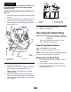
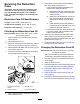
7.Usingaspring-removaltool(T oroPartNo.
92-5771),removethespringfromtheanchor
bracketontheenginedeck(Figure48).
Note:Leavetheotherendofthespring
attachedtotheframeofthemachine.
g020119
Figure48
1.Anchorbracket
4.Spring-removaltool
(springremoved)
2.Enginedeck
5.Spring(springremoved)
3.Spring-removaltool(Toro
PartNo.92-5771)
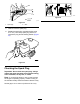
8.Removetheboltandnutthatsecuretherear
bracketfortheenginedeckhingetotheframe
ofthemachine(Figure49).
g020120
Figure49
1.Enginedeck4.Frame
2.Pivot5.Nut
3.Rearhingebracket6.Bolt
9.Liftuptherearedgeoftheenginedeckand
removethehingebracket(Figure49).
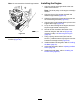
10.Slidetheenginedeckrearwardandoutfromthe
forwardhingebracket(Figure50).
35