
Operator's Manual
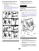
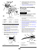
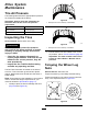

8.Removetheboltandnutthatsecuretherear
bracketfortheenginedeckhingetotheframe
ofthemachine(Figure50).
g020120
Figure50
1.Enginedeck
4.Frame
2.Pivot5.Nut
3.Rearhingebracket6.Bolt
9.Liftuptherearedgeoftheenginedeckand
removethehingebracket(Figure50).
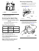
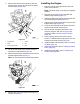
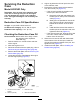
10.Slidetheenginedeckrearwardandoutfromthe
forwardhingebracket(Figure51).
Note:Donotremovetheforwardhingebracket.
g020121
Figure51
11.Removetheengineandenginedeckfromthe
machine(Figure51).
InstallingtheEngine
1.Aligntheengineandenginedecktotherear
frameofthemachine.
Note:Thedrivepulleyontheenginemustalign
forward.
2.Alignthepivotontheenginedeckwiththe
forwardhingebracket(Figure51).
3.Slidetheenginedeckforwardandthepivotinto
theforwardhingebracket(Figure51).
4.Aligntherearhingebracketwiththepivotonthe
engine-deckhinge(Figure51).
5.Liftupontherearedgeoftheenginedeckand
slipthehingebracketontothepivot.
6.Securetherearbrackettotheframeofthe
machineusingtheboltandnut(Figure50)
removedinstep8ofRemovingtheEngine
(page35).
7.Usingaspring-removaltool(T oroPartNo.
92-5771),installthetensionspringtotheanchor
bracketontheenginedeck(Figure49).
8.Installthebeltsandbeltguide;refertoInstalling
theBelts(page43).
9.Adjustthebeltguide;refertoAdjustingtheBelt
Guide(page44).
10.Installthedividerplate;refertoInstallingthe
DividerPlate(page28).
36