Form No. 3422-822 Rev A MMX-658K-P, MMX-858K-P, and MMX-858H-P Mortar Mixers Model No. Model No. Model No. Model No. Model No. Register at www.Toro.com. Original Instructions (EN) 60217—Serial No. 400000000 and Up 60217C—Serial No. 400000000 and Up 60221—Serial No. 400000000 and Up 60221C—Serial No. 400000000 and Up 60221HD—Serial No.
It is a violation of California Public Resource Code Section 4442 or 4443 to use or operate the engine on any forest-covered, brush-covered, or grass-covered land unless the engine is equipped with a spark arrester, as defined in Section 4442, maintained in effective working order or the engine is constructed, equipped, and maintained for the prevention of fire.
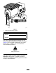
g249187 Figure 1 1. Model and serial number location Model No. Serial No. This manual identifies potential hazards and has safety messages identified by the safety-alert symbol (Figure 2), which signals a hazard that may cause serious injury or death if you do not follow the recommended precautions. g000502 Figure 2 Safety-alert symbol This manual uses 2 words to highlight information.
Contents Aligning the Pulleys .......................................... 46 Paddle Maintenance ............................................ 47 Adjusting the Paddles ....................................... 47 Cleaning .............................................................. 49 Cleaning the Machine ....................................... 49 Storage ................................................................... 49 Troubleshooting ...................................................... 51 Safety ...
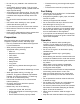
Safety • Read and understand the contents of this Operator’s Manual before you start the engine. Ensure that everyone using this product knows how to use it and understands the warnings. Improper use or maintenance by the operator or owner can result in injury. To reduce the potential for injury, comply with these safety instructions and always pay attention to the safety-alert symbol (Figure 2), which means: Caution, Warning, or Danger—personal safety instruction.
• Do not carry any material in the machine when • • • • • • • – Ensure that the lug nuts are tight and torqued properly. – Ensure that the machine is properly secured. towing. Avoid sudden stops and starts. This can cause skidding or jackknifing. Smooth, gradual starts and stops improves towing. Avoid sharp turns to prevent rolling. Tow only with a vehicle that has a hitch designed for towing. Do not attach towed equipment except at the hitch point. Do not tow the machine faster than 88 km/h (55 mph).
• Ensure that all the guards and shields are securely in place before operating the machine. • If the mixing paddles strike an object or if the machine starts making an unusual noise or vibration, shut off the engine, wait for all moving parts to stop, and empty the drum. Inspect for clogging or damage. Clean, repair, and/or replace any damaged parts. • Do not change the engine governor setting or overspeed the engine. • Do not operate the machine when there is the risk of lightning.
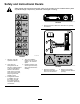
Safety and Instructional Decals Safety decals and instructions are easily visible to the operator and are located near any area of potential danger. Replace any decal that is damaged or missing. decal125-8175 125-8175 1. Read the Operator’s Manual for information on greasing the machine. decal125-4939 125-4939 1. Warning—read the Operator’s Manual. 4. Toxic gas inhalation hazard—Do not run the engine in an enclosed space. 2.
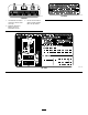
decal133-5619 133-5619 decal130-8322 130-8322 1. Use fuel with an alcohol content by volume under 10% only. 3. Do not use fuel with an alcohol content greater than 10% by volume. 2. Read the Operator's Manual for more information on fuel.
decal137-7491 137-7491 1. Read the Operator’s Manual.
Setup Loose Parts Use the chart below to verify that all parts have been shipped. Procedure Description Use Qty. 1 Dump handle Carriage bolt Nut 1 2 2 Install the dump handle. 2 Tow pole kit (sold separately) 1 Install the tow pole (side-dump models only). 3 Safety chain (included with the tow pole kit) Connecting link (included with the tow pole kit) 4 No parts required 1 Install the safety chain. 2 – Adjust the mixing paddles.
4. 2 Thread the nut onto the bolt and tighten them until they are tight against the frame fitting (Figure 4). Note: If the self-locking nylon insert in the Installing the Tow Pole locknut wears with use, replace the nut with a new Grade 5 or Grade 8 locknut. Parts needed for this procedure: 1 3 Tow pole kit (sold separately) Tow Pole Specifications Installing the Safety Chain Purchase the tow pole kit (including fasteners) that meets your needs from your Authorized Service Dealer.
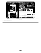
Product Overview 4 Adjusting the Mixing Paddles No Parts Required Procedure Adjust the paddle blades to be as close as possible to the inner walls of the drum; refer to Adjusting the Paddles (page 47). g232184 Figure 6 Right side 1. Rear cowl 2. Front cowl 3. Grate 13 7. Clutch lever 8. Drum latch 9. Front post 4. Bag splitter 10. Tow pole 5. Dump handle 11. Safety-chain keyhole 6. Grate lift arm 12. Drum 13. Chute 14. Axle 15. Cowl latch 16.
Controls Dump Handle Become familiar with all the controls before you start the engine and operate the machine. Use the dump handle to rotate the drum to the dump position and to rotate the drum to the mix position (upright). Clutch Lever Use the clutch lever to engage and disengage the paddles. g232185 Figure 9 g019875 1. Dump handle Figure 7 1. Clutch lever Drum Latch Use the drum latch to secure the drum to the mix position (upright) for mixing operations and when transporting the machine.
Engine Controls Fuel Valve The fuel valve (Figure 12 and Figure 13) is located underneath the choke lever. Move the lever for the fuel valve to the ON position before attempting to start the engine. When you have finished mixing, shut off the engine and move the fuel-valve lever to the OFF position. g019744 Figure 10 Model 60221HD shown 1. Recoil-start handle 5. Fuel cap 2. Fuel valve 6. Oil dipstick 3. Choke lever 7. Oil-drain plug 4. Throttle lever 8.
the engine is running, move the choke lever to the OPEN position. Do not use the choke if the engine is already warmed up or if the air temperature is high. Throttle Lever The throttle lever (Figure 12 and Figure 11) controls the speed (rpm) of the engine. It is located next to the choke lever. It sets the engine speed and therefore can increase and decrease the rotation speed of the mixing paddles. For best performance, set this control to the FAST position when mixing material.
Specifications Note: Specifications and design are subject to change without notice. Machine Specifications Model 60217, 60217C m3 (6.0 ft3) 60221HD 60221, 60221C 0.23 m3 (8.0 ft3) 0.23 m3 (8.0 ft3) Batch Capacity 0.17 Total Volume 0.19 m3 (6.7 ft3) 0.24 m3 (8.6 ft3) 0.24 m3 (8.
WARNING Towing the machine with material in the drum increases the risk of a hitch malfunction and tire failure. In addition, material could bounce out of the drum and hit other vehicles and/or people. Material in the drum increases the weight, which affects momentum and braking distance. Do not tow the machine with material in the drum. • Review and understand the Safe Operating Practices (page 5). • Test the brakes of the tow vehicle before towing.
g035115 Figure 18 Note: Use a wrench to keep the bolt from spinning. Hitching a Pintle-Hitch Coupler g035113 Figure 17 Hitching a Forged-Ball Coupler 1. Apply removable thread-locking compound to the threads of the coupler bolt to prevent the coupler handle from coming loose. Important: Apply thread-locking compound as needed in the future. 2. Apply chassis grease to the socket of the coupler and the area of the clamp that contacts the ball. 3. Hitch the machine as shown in Figure 18.
Connecting the Safety Chains to the Tow Vehicle 1. Pull the safety chain through the slots in the keyholes, so that the lengths on each side are equal. 2. Cross both lengths of chain under the tow pole. Note: Crossing the chains decreases the chances of the front of the machine dropping to the ground if the hitch does not hold the connection. g019927 Figure 21 1. Connecting link 3. Chain link 2. Safety chain mounting point on tow vehicle 4.
The corresponding turn-signal lights of the machine should illuminate. Adjusting the Axle Width Models with Adjustable Axles Only If your model is equipped with an adjustable axle (Figure 24), you can adjust the axle to the narrow position to move the machine through a narrow access point, such as the gate of a fence or the doorway of a building. WARNING The machine is not stable when towed with the axle in the narrow position. g029390 Figure 23 Tow the machine with the axle in the wide position. 1.
2. Ensure that all guards and paddles are in place and in good condition. 3. Perform all daily maintenance procedures prescribed in Maintenance (page 28). 4. Chock the front and back of the tires to prevent the machine from moving. 5. Move the drum to the upright position and lock it. Closing the Cowl Opening the Cowl g035135 Figure 26 Adding Fuel DANGER In certain conditions, fuel is extremely flammable and highly explosive.
• Do not store fuel either in the fuel tank or in fuel DANGER containers over the winter unless you use a fuel stabilizer. In certain conditions during fueling, static electricity can be released, causing a spark that can ignite the fuel vapors. A fire or explosion from fuel can burn you and others and can damage property. • Always place fuel containers on the ground away from your vehicle before filling.
Important: This space in the tank allows fuel to expand. Do not fill the fuel tank completely full. g019815 Figure 29 1. Choke lever 2. Fuel valve 3. g020679 Figure 28 Model 60221HD engine shown 3. Throttle lever Move the choke lever to the ON position (Figure 29). Note: A warm or hot engine may not require choking. 1. Maximum fuel level 4. Move the throttle lever 1/3 of the way toward the MAX position. 4.
DANGER This machine is capable of amputating hands. • Stay in the operator’s position while the machine is running. • Keep all bystanders a safe distance away from the machine. • Stop the machine immediately if any people or animals enter the work area. • Never place any part of your body into a position that causes an unsafe operating condition. g019747 Figure 31 Model 60221HD shown Important: Do not add more material than the batch capacity of the machine; refer to Specifications (page 17). 7.
7. Allow the paddles to mix the material until the ingredients have a uniform appearance. Note: If needed, add water or plaster, cement, or other binding material until the consistency of the batch is correct. Dumping the Material DANGER Contact with the mixing paddles could cause damage or injury. Never put your hands inside the drum while the engine is running.
4. With both hands on the dump handle, rotate it counterclockwise to discharge the contents of the drum (Figure 34). Note: Allow the machine to completely discharge the contents of the drum. 5. Rotate the dump handle clockwise until the drum latch locks the drum in the upright position (Figure 34). 6. After dumping a batch of material, clean the drum to prevent dried material from contaminating the next batch of material; refer to Cleaning the Drum (page 27).
Maintenance WARNING Failure to properly maintain the machine could result in premature failure of machine systems causing possible harm to you or bystanders. Keep the machine well maintained and in good working order as indicated in these instructions. Important: Refer to your engine operator's manual for additional maintenance procedures. Recommended Maintenance Schedule(s) Maintenance Service Interval Maintenance Procedure After the first 20 hours • Change the reduction-case oil (Model 60221HD only).
Pre-Maintenance Procedures Preparing the Machine for Maintenance 1. Shut off the engine and allow it to cool completely. 2. Park the machine on a level surface. 3. Remove the machine from the tow vehicle. 4. Secure the machine from movement. 5. Disconnect the spark-plug wire. g232217 Figure 36 3. To remove the divider plate, lift it upward and tilt it back so that it clears various components.
Lubrication Lubricating the Bearings, Seals, and Gears Service Interval: After each use—Lubricate the trunnions. Monthly—Lubricate the pillow-block bearings. Every 100 hours—Lubricate all the gear teeth around the paddle-drive gear and pinion gear. g250569 Note: The pillow-block bearings are inside the cowl—remove the divider plate (if equipped) to access them; refer to Removing the Divider Plate (page 29). Grease Type: No. 2 lithium grease. 1.
Engine Maintenance Servicing the Air Cleaner Service Interval: Before each use or daily—Inspect the air-cleaner elements. Every 50 hours—Clean the air-cleaner elements. Clean them more frequently in dusty operating conditions. Every 300 hours/Yearly (whichever comes first)—Replace the paper air-cleaner element. Replace it more frequently in dusty operating conditions. Important: Do not operate the engine without the air-filter assembly; extreme engine damage will occur. 1.
11. Wipe dirt from the base and the cover with a moist rag. Note: Be careful to prevent dirt and debris from entering the air duct leading to the carburetor. 12. Install the air-cleaner elements and ensure that they are properly positioned. 13. Securely install the cover with the nut. Servicing the Engine Oil Engine-Oil Specifications Toro Premium Engine Oil is available from your Authorized Toro Dealer.
Checking the Engine-Oil Level Changing the Engine Oil Service Interval: Before each use or daily Service Interval: After the first 25 hours Every 100 hours 1. Park the machine on a level surface and shut off the engine. 2. Allow the engine to cool. 3. Disconnect the wire from the spark plug; refer to Disconnecting the Spark-Plug Wire (page 29). 4. Clean around the dipstick. 5. Check the oil level as shown in Figure 42.
Removing the Spark Plug 1. Park the machine on a level surface and shut off the engine. 2. Ensure that the machine surfaces are cool. 3. Pull the spark-plug wire off the terminal of the spark plug (Figure 45). g028981 Figure 44 1. Oil-fill hole 3. Oil-level upper limit 2. Dipstick 4. Oil-level lower limit 7. Replace and secure the dipstick. 8. Wipe up any spilled oil. g014506 Figure 45 Servicing the Spark Plug 1.
Checking the Spark Plug Cleaning the Spark Arrester Important: Do not clean the spark plug. Always replace the spark plug when it has a black coating, worn electrodes, an oily film, or cracks. Service Interval: Every 100 hours Note: A spark arrester is available as an option. If you require a spark arrester, contact your Authorized Toro Service Dealer. Genuine Toro spark arresters are approved by the USDA Forestry Service.
10. Install the spark arrester, muffler protector, exhaust deflector, and muffler in the reverse order of disassembly. 11. Install the divider plate (if equipped); refer to Installing the Divider Plate (page 29). Removing and Installing the Engine Removing the Engine WARNING The spring is under tension when installed and can cause personal injury. Be careful when removing the spring. g019331 Figure 48 Model 60221HD shown 1. Deflector (if applicable) 5. Exhaust pipe 2. Protector 6. Nut (8 mm) 10.
8. Installing the Engine Remove the bolt and nut that secure the rear bracket for the engine deck hinge to the frame of the machine (Figure 51). 1. Align the engine and engine deck to the rear frame of the machine. Note: The drive pulley on the engine must align forward. 2. Align the pivot on the engine deck with the forward hinge bracket (Figure 52). 3. Slide the engine deck forward and the pivot into the forward hinge bracket (Figure 52). 4.
Fuel System Maintenance Cleaning the Fuel-Sediment Cup 8. Wipe the O-ring with a clean, dry cloth. 9. Install the fuel filter in the bottom of the carburetor (Figure 53). 10. Align the O-ring in to the groove in the sediment cup and install the sediment cup to the fuel-valve housing. 11. Move the lever of the fuel valve to the ON position (all the way to the right) and check for leaks. If it leaks, replace the O-ring.
Electrical System Maintenance Servicing the Light Bulbs For Models 60217C, 60221C, 60221C Replacing the Rear-Facing Side Bulbs g020830 Figure 57 Note: The left rear-facing bulb also illuminates license plate. 1. Use a screwdriver to remove the 4 screws from the large square lens on the light (Figure 56). 2. Remove the lens (Figure 57). 3. Pull the bulb out of the socket (Figure 57). 4. Push a new 168 bulb into the socket (Figure 57). 5. Install the lens and the 2 screws (Figure 57).
Drive System Maintenance Tire Air Pressure The following table shows the appropriate air pressure for the tires as installed at the factory. g020836 Figure 59 Important: Always check the information on the actual tires for the correct air pressure requirement. Model Maximum Air Pressure 60217, 60217C 414 kPa (60 psi) 60221, 60221C, 60221HD 241 kPa (35 psi) 1.
Servicing the Reduction Case 6. Align a rag below the oil-level port in the side of the reduction case. 7. Remove the oil-level-check bolt and washer from the oil-level port (Figure 62). Model 60221HD Only • If the oil level is below the threads in the Important: If the oil level in the reduction case oil-level port, add oil as follows: is too low or too high and you run the engine, you may damage the engine or the reduction case. This type of damage is not covered by the warranty.
Changing the Reduction-Case Oil Service Interval: After the first 20 hours—Change the reduction-case oil (Model 60221HD only). Every 100 hours/Every 6 months (whichever comes first)—Change the reduction-case oil (Model 60221HD only). 1. Park the machine on a level surface and shut off the engine. 2. Allow the engine to cool. 3. Disconnect the wire from the spark plug; refer to Disconnecting the Spark-Plug Wire (page 29). 4. Remove the engine; refer to Removing the Engine (page 36).
Belt Maintenance Inspecting the Belts Service Interval: After the first 25 hours—Inspect the belts and adjust as necessary (belt-drive models only). Every 40 hours—Inspect the belts and adjust as necessary (belt-drive models only). 1. Park the machine on a level surface and shut off the engine. 2. Allow the machine to cool. 3. Disconnect the wire from the spark plug; refer to Disconnecting the Spark-Plug Wire (page 29). 4. Remove the divider plate; refer to Removing the Divider Plate (page 29). 5.
5. Remove the divider plate; refer to Removing the Divider Plate (page 29). 6. Remove the bolt that secures the belt guide to the engine, and remove the belt guide (Figure 68). g020010 Figure 68 g020009 Figure 67 1. Bolt 1. Engine pulley 5. Idler shaft 2. Idler pulley 6. Jam nut 3. Reduction case (engine) 7. Setscrew 4. Belt guide 8. Straightedge E. If necessary, pivot the engine on the engine deck until the engine pulley and idler pulley are aligned to the straightedge (Figure 67). F.
3. Disconnect the wire from the spark plug; refer to Disconnecting the Spark-Plug Wire (page 29). 4. Ensure that the clutch lever is in the OFF position. 5. Align the rear belt to the rear groove in the engine pulley. Note: Do not align the rear belt to the idler pulley. 6. Align the forward belt to the forward groove of the idler pulley. 7. Slip the rear belt over the idler pulley and align the belt to the rear pulley groove. 8.
4. Aligning the Pulleys A. Shut off the engine. B. Check the air gap between the belt guide and the belts. 1. Park the machine on a level surface and shut off the engine. Note: If the air gap is larger than 4.0 mm (5/32 inch), decrease the gap between the belt guide and the belts; refer to Adjusting the Belt Guide (page 45). 2. Allow the machine to cool. 3. Disconnect the wire from the spark plug; refer to Disconnecting the Spark-Plug Wire (page 29).
Paddle Maintenance Adjusting the Paddles Important: Complete the Preparing the Machine for Maintenance (page 29) before adjusting any of the paddles. Note: Over time, you may need to adjust the mixer paddles to account for wear. g029188 Figure 73 Aligning the Circumferential-Drum Wipers 1. 2. Rotate a paddle from the left row of paddles around the drum and locate at the interior of the drum the smallest distance between the drum and the wiper of the paddle (Figure 72). 1. Wiper 4. Paddle blade 2.
Aligning the Adjustable-End Paddles Aligning the End-Paddle Wipers 1. 2. Rotate the wiper and fixed paddle around the end plate of the drum and locate smallest distance between the drum and the wiper of the paddle. Mark the inside of the end plate at the location that you determined in step 1. 1. Align the adjustable-end paddle to the mark that you made in step 2 of Aligning the End-Paddle Wipers (page 48). 2.
Cleaning Storage For storage over 30 days, prepare the machine as follows: 1. Remove dirt and grime from the external parts of the entire machine, especially the engine. Clean dirt and debris from the outside of the engine cylinder-head fins and blower housing. Cleaning the Machine Regular cleaning and washing with mild detergent and water increases the life span of the machine. Clean the machine after each use before the dirt hardens.
Note: Do not install the wire on the spark plug. 8. Grease the machine; refer to Lubricating the Bearings, Seals, and Gears (page 30). 9. Check and tighten all bolts, nuts, and screws. Repair or replace any part that is damaged. 10. Paint all scratched or bare metal surfaces with paint available from your Authorized Service Dealer. 11. Store the machine in a clean, dry garage or storage area. 12. Cover the machine to protect it and keep it clean.
Troubleshooting Problem The engine does not start. Possible Cause 1. The fuel-valve lever is in the OFF position. 1. Move the fuel-valve lever to the ON position. 2. The choke is closed 2. Open the choke when starting a hot engine. 3. Close the choke when starting a cold engine. 4. Rotate the switch to the ON position. 3. The choke is open. 4. The engine On/Off switch is in the OFF position. 5. The engine oil level is low (engines with the oil-level switch). 6. The fuel tank is empty. 7.
Notes:
Notes:
Notes:
California Proposition 65 Warning Information What is this warning? You may see a product for sale that has a warning label like the following: WARNING: Cancer and Reproductive Harm—www.p65Warnings.ca.gov. What is Prop 65? Prop 65 applies to any company operating in California, selling products in California, or manufacturing products that may be sold in or brought into California.
The Toro Warranty A limited warranty (see warranty periods below) Conditions and Products Covered The Toro Company and its affiliate, Toro Warranty Company, pursuant to an agreement between them, jointly warrant your Toro Concrete, Masonry, and Compaction Equipment Products listed below to be free from defects in materials or workmanship. This warranty covers the cost of parts and labor, but you must pay transportation costs. for that part.