Form No. 3378-862 Rev A CM-250E-PC and CM-250E-PWB Concrete Mixer Model No. 68001—Serial No. 313000001 and Up Model No. 68003—Serial No. 313000001 and Up g021660 Register at www.Toro.com.
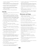
WARNING 1 CALIFORNIA Proposition 65 Warning This product contains a chemical or chemicals known to the State of California to cause cancer, birth defects, or reproductive harm. Use of this product may cause exposure to chemicals known to the State of California to cause cancer, birth defects, or other reproductive harm. g021796 Figure 1 Introduction 1. Model and serial number plate This machine is designed to mix concrete products.
Contents Safety Introduction .................................................................. 2 Safety ........................................................................... 3 Safe Operating Practices........................................... 3 Safety and Instructional Decals ................................. 5 Setup ............................................................................ 6 1 Installing the Wheels and Axle ................................ 6 2 Installing the Frame Stop ........
• Connect the machine only to a 3-pole receptacle with live, protection. Long hair, loose clothing, or jewelry may get tangled in moving parts. neutral, and ground circuits. • Whenever possible, use circuits or receptacles protected • When using an extension cord and an in-line Ground with a Ground Fault Circuit Interrupter (GFCI) device. Fault Circuit Interrupter (GFCI) device, install the GFCI device as close to the electrical source as possible. • Inspect the electrical cords for damage.
Safety and Instructional Decals Safety decals and instructions are easily visible to the operator and are located near any area of potential danger. Replace any decal that is damaged or lost. 121–6161 1. Entanglement hazard, belt—keep hands away from moving parts; keep all guards and safeties in place. 125–8176 1. Warning—read the Operator’s Manual. 2. Electric shock hazard—properly ground equipment before use. 125–4971 1. Read the Operator’s Manual. 5 3.
Setup Note: If you are not using the pedestal, you may use a spacer axle piece instead of the pivot mount plate. 3. Secure the wheels and axle rod in place with cotter pins; refer to Figure 3.
3 4 Installing the Motor Installing the Drum Parts needed for this procedure: Parts needed for this procedure: 1 Electric Motor 1 Drum 4 Nut 1 Bolt 4 Washer 1 Nut 4 Lock Washer Procedure Procedure 1. Move the drum into place; refer to Figure 6. 1. Move the motor into position on the frame of the machine; refer to Figure 5. 1 23 1 4 2 g022157 Figure 6 1. Drum g022156 2. Motor Figure 5 1. Nut 2. Lock washer 2. Connect the drum to the motor with the bolt and nut.
2 1 3 3 2 1 4 g022158 g022175 Figure 7 1. Bolt 2. Nut Figure 8 3. Drum 4. Motor 1. Motor cover 2. Bolts 5 6 Installing the Motor Cover Installing the Handlebars Parts needed for this procedure: 1 Motor cover 2 Bolt 2 Nut 3. Nuts Parts needed for this procedure: 2 Handlebar 2 Handlebar Grips Procedure Procedure 1. Slide handlebars into place, and secure them using the locking pin (Figure 9). Fasten motor cover to the frame of the machine; refer to Figure 8.
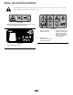
Product Overview 2 3 1 3 1 2 4 g021662 Figure 10 1. Dump handles 3. Drum 2. Power cord 4. Electric motor g021663 Figure 11 1. Power cord 2. Reset button Controls 3. On/Off switch Motor Controls Specifications Become familiar with all the controls before you start the motor and operate the machine. Note: Specifications and design are subject to change without notice. Capacity: Concrete Volume Total (wet) Length Width 127 cm (50 inches) 61.6 cm (24.25 inches) Height 101.
Operation damaged cord. Do not run the cord through standing water or wet grass. Important: Before operating, remove debris from the machine. Also, ensure that the area is clear of people and debris. Important: Use only 3-wire extension cords with terminals and sockets for the live, neutral, and ground circuits. Operating the Machine Important: Only connect the machine to a 3-pole receptacle with live, neutral, and ground circuits. • Review all of the safety decals.
Starting and Stopping the Motor Using the Pedestal Starting the Electric Motor Assembling the Pedestal Note: For Model 68001 only 1. Place 2 halves of the support legs together, and insert pivot tube through the center of the legs (Figure 13). Important: Check any extension cord carefully for broken connectors, bare wires, or damaged insulation. Do not use any cord found to be in poor condition. Make sure that the extension cord is not routed through standing water and that all connections are tight.
Attaching Pedestal Stand to the Machine 1. Tip the mixer, as if dumping contents, and place it squarely on the drum opening. CAUTION The pivot mount will rotate freely about the axle when tipping the mixer onto the drum opening. The rotating pivot mount can cause pain and injury to legs. Stand clear of wheel axle. 2. Rotate the pivot mount plate away from the drum and onto the front stop (Figure 14). 1 2 g019656 Figure 15 Figure 14 1. Pivot mount 2. Frame stop 4.
Mixing Pre-Mix Concrete WARNING 1. Turn the machine on. Do not tilt mixer upright onto stand on a wet, uneven, or slippery surface. Failure to follow this instruction could result in personal injury and damage to the equipment. 2. Pour water into the drum. 3. Add the required amount of dry pre-mix concrete. 4. Allow the drum to turn while the mix reaches the appropriate consistency. Set up the pedestal on flat ground with plenty of traction before attempting to tilt the machine upright onto the stand.
Maintenance Recommended Maintenance Schedule(s) Maintenance Service Interval Maintenance Procedure • Remove debris from the machine. • Clean the machine. After each use • Drain and replace the oil in the gearbox. Every 200 hours Important: Refer to your Motor Operator's Manual for additional maintenance procedures. Lubrication Cleaning Oil the Gearbox Coat the drum and frame with a concrete preventative. This will make cleaning the machine easier.
Storage For storage over 30 days, prepare the machine as follows: 1. Remove dirt and grime from the external parts of the entire machine, especially the motor. Clean dirt and concrete from the inside and outside of the drum; refer to Cleaning (page 14). 2. Check and tighten all bolts, nuts, and screws. Repair or replace any part that is damaged. 3. Paint all scratched or bare metal surfaces. Paint is available from your Authorized Service Dealer. 4.
Troubleshooting Problem The electric motor will not start. The motor runs but the mixer rotation is underpowered. Possible Cause Corrective Action 1. The connector for the machine is not plugged in to a power source. 1. Plug the connector into a socket or and extension cord from an electrical source. 2. The current protector for the electrical source is open. 2. Reset the circuit protector. 1. The drum is overfilled. 1. Dump out concrete until the motor runs at full power. 2.
Notes: 17
Notes: 18
Notes: 19
Toro Compact Utility Equipment Warranty A One-Year Limited Warranty Conditions and Products Covered The Toro® Company and its affiliate, Toro Warranty Company, pursuant to an agreement between them, jointly warrant your Toro Compact Utility Equipment (“Product”) to be free from defects in materials or workmanship.