Form No. 3405-114 Rev A CM-Series Concrete Mixers Model No. Model No. Model No. Model No. Model No. 68004—Serial No. 68006—Serial No. 68007—Serial No. 68008—Serial No. 68009—Serial No. 314000001 and Up 314000001 and Up 314000001 and Up 314000001 and Up 314000001 and Up G019544 Register at www.Toro.com.
You may contact Toro directly at www.Toro.com for product safety and operation training materials, accessory information, help finding a dealer, or to register your product. WARNING CALIFORNIA Proposition 65 Warning This product contains a chemical or chemicals known to the State of California to cause cancer, birth defects, or reproductive harm. The engine exhaust from this product contains chemicals known to the State of California to cause cancer, birth defects, or other reproductive harm.
Contents Safety ........................................................................... 4 Safe Operating Practices........................................... 4 Safety and Instructional Decals ................................. 7 Setup ...........................................................................10 1 Installing the Tow Pole..........................................10 2 Installing the Tongue ............................................10 3 Installing the Safety Chain .........................
Safety • Never let children or untrained people operate or service the equipment. Local regulations may restrict the age of the operator. Improperly using or maintaining the machine can result in injury. To reduce the potential for injury, comply with these safety instructions and always pay attention to the safety alert symbol , which means: Caution, Warning, or Danger—personal safety instruction. Failure to comply with the instruction may result in personal injury or death.
Preparation – Ensure that the lug nuts are tight and torqued properly. Become familiar with the safe operation of the equipment, operator controls, and safety signs. • Use only accessories and attachments approved by the manufacturer.
Maintenance and Storage • Before performing maintenance, do the following: – Park the machine on level ground. – Shut off the engine. Wait for all movement to stop before adjusting, cleaning, or repairing. – Let the engine cool before performing maintenance or storing. – Disengage all power and operation controls. • Never lubricate, service, repair, or adjust the machine while it is running. • Keep equipment materials clear from the muffler and engine to help prevent fires.
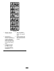
Safety and Instructional Decals Safety decals and instructions are easily visible to the operator and are located near any area of potential danger. Replace any decal that is damaged or lost. 117-2718 125-8216 125-4940 1. Warning 1. Read the Operator’s Manual for information on how to tow the machine. 3. Engine—shut off 2. Engine—run 2. Warning—limit towing speed to less than 55 mph / 88 km/h. 125-8175 1. Read the Operator’s Manual for information on greasing the machine. 130-8322 1.
125-4939 1. Warning—read the Operator’s Manual. 4. Toxic gas inhalation hazard—Don’t run the engine in an enclosed space. 2. Hand and arm entanglement at the belt drive; crushing hazard of hand; entanglement hazard of hand at the shaft—keep hands away from moving parts; keep all guards and shields in place. 5. Explosion hazard—shut off the engine and keep away from flames when refueling. 3.
132-4041 1. Read the Operator's Manual for more information on servicing the machine. 132-4042 1. Read the Operator's Manual for more information on servicing the machine.
Setup Loose Parts Use the chart below to verify that all parts have been shipped. Procedure 1 2 3 Description Qty. Use Tow pole kit (sold separately) 1 Install the tow pole (side-dump models only). Tongue Front stabilizer leg Short bolt Long bolt Nut Safety chain Connecting link 1 1 6 1 7 1 2 1 1 Install the tongue (end-dump models only). Install the safety chain.
2 Installing the Tongue End-Dump Models Only 1 Parts needed for this procedure: G021092 1 Tongue 1 Front stabilizer leg 6 Short bolt 1 Long bolt 7 Nut Figure 6 1. Front stabilizer leg 4. Install the tongue into the opening at the front of the machine and secure it with 6 nuts and short bolts torqued to 102 N∙m (75 ft-lb); refer to Figure 7. Installing the Tongue to the Machine 1 2 3 1. Lower the rear stabilizer legs; refer to Lowering the Stabilizer Legs (page 21). 2.
Installing the Safety Chain 3 End-Dump Models Only Installing the Safety Chain Parts needed for this procedure: 1 Safety chain 2 Connecting link Installing the Safety Chain Side-Dump Models Only Form a hook on the end of a bendable piece of rod or stiff wire, (not included), and install the safety chain as shown in Figure 8. Figure 9 Note: Ensure that approximately equal lengths of safety chain extend from either side of the tongue.
Product Overview 5 3 6 4 2 1 7 3 4 2 8 1 11 8 7 11 6 5 G019730 Figure 10 Side-Dump Models 1. Engine cowl 5. Tow pole 2. Engine switch 6. Safety-chain keyholes 3. Drum 4. Handwheel 7. Drum-tilt brake 8. Rubber latch 10 12 9 G019914 Figure 11 End-Dump Models 1. Tongue-mounted tow coupler 7. Handwheel 2. Safety-chain keyholes 8. Drum-tilt brake 3. Rubber latch 9. Front stabilizer leg 4. Engine switch 13 10. Rearward pin hole 5. Engine cowl 11. Clevis pin 6. Drum 12.
Controls 1 3 2 Become familiar with all of the controls before you start the engine and operate the machine. Engine Switch When the engine switch on the cowl is in the RUN position, it allows the engine to run. Moving the engine switch to the STOP position shuts off the engine. Handwheel The handwheel controls the discharging action of the drum. G018792 Drum-tilt Brake Figure 13 The drum-tilt brake locks the drum into an upright position or a discharging position. 1. Fuel valve 2. Choke lever 3.
Recoil-Start Handle Oil-Level Switch To start the engine, pull the recoil-start handle (Figure 12) quickly to turn the engine over. The engine controls described above must all be set correctly for the engine to start. The oil-level switch is located inside the engine, and it does not allow the engine to run in the event the oil level is below the safe operating limit. Specifications Note: Specifications and design are subject to change without notice.
1 G020836 Figure 17 1. Example of tire wear caused by underinflation 2 G019733 Figure 16 Drum-Tilt Brake 1. Unlocked position 2. Locked position Figure 18 1. Example of tire wear caused by overinflation 4. Ensure that the engine cowl is closed and latched; refer to Closing the Cowl (page 22). 2. Ensure that the tires are inflated to the correct air pressure. The following Tire Air Pressure table shows the appropriate air pressure for the tires as installed at the factory. 5.
7. Pull the clevis pin out from the front stabilizer leg and the tongue (Figure 21). 1 3 3 4 2 G021 107 Figure 19 2 1 Raising the Stabilizer Legs End-Dump Models Only G019915 End-dump models have a front stabilizer leg and 2 rear stabilizer legs. Figure 21 1. Remove the clevis pin. Raise the stabilizer legs before towing the machine. 3. Install the clevis pin. 2. Rotate the stabilizer leg up. 1. Adjust the machine so that there is no weight resting on the rear stabilizer legs. 2.
Hitching a Machine with a Stamped Ball Coupler Hitching a Machine with a Forged Ball Coupler 1. Apply chassis grease to the socket of the coupler and the area of the clamp that contacts the ball. 1. Apply removable thread-locking compound to the threads of the coupler bolt to prevent the coupler handle from coming loose. 2. Oil the pivot points and sliding surfaces of the coupler with SAE 30 motor oil. Important: Apply thread-locking compound as needed in the future. 3.
Hitching a Machine with a Pin Hitch Coupler Hitching a Machine with a Pintle Hitch Coupler 1. Using a 19 mm (3/4 inch) or 22 mm (7/8 inch) hitch pin, hitch the machine as shown in Figure 25. 1. Hitch the machine as shown in Figure 24. Figure 25 Figure 24 2. If the machine is equipped with a trailer-light kit, connect the wire plug of the tow vehicle to the wire plug of the machine. 2.
Connecting the Safety Chains to the Tow Vehicle Important: Ensure that the chain has enough slack for turning around corners when towing the machine. 1. Pull the safety chain through the slots in the keyholes, so that the lengths on each side are equal. Note: For side-dump models, stow the excess chain inside the bottom of the front post by pushing it into the keyholes and latching the appropriate links into the keyhole slots. 2.
Towing the Machine 3. Chock the front and back of the tires to prevent the machine from moving. WARNING 4. Ensure that the drum is in the mix position (upright). Towing the machine at high speed increases the risk of a hitch malfunction and tire failure. Higher speeds also increase the momentum of the machine and braking distance. If the machine becomes detached from the tow vehicle at high speed, it could cause damage to property, or injury or death to bystanders. 5.
Closing the Cowl 1 2 3 G019916 Figure 30 1. Remove the clevis pin. 3. Install the clevis pin. 2. Rotate the stabilizer leg down. 7. Rotate the front stabilizer leg down toward the ground (Figure 30). Figure 32 8. Push the clevis pin through the front hole in the tongue and the front stabilizer leg (Figure 30) and carefully lower the machine to the ground.
DANGER WARNING In certain conditions, fuel is extremely flammable and highly explosive. A fire or explosion from fuel can burn you and others and can damage property. Fuel is harmful or fatal if swallowed. Long-term exposure to vapors can cause serious injury and illness. • Fill the fuel tank outdoors, in an open area, when the engine is cold. Wipe up any gasoline that spills. • Avoid prolonged breathing of vapors. • Keep face away from nozzle and fuel tank or conditioner bottle opening.
1 4. Install the fuel cap securely (Figure 33). 5. Wipe up any fuel that may have spilled. Checking the Engine-Oil Level Before you start the engine and use the machine, check the oil level in the engine crankcase; refer to Checking the Engine-Oil Level (page 32). Starting and Shutting Off the Engine Starting the Engine 1. On the engine cowl, move the engine switch to the ON position (Figure 35). G019799 1 Figure 33 1. Fuel cap 3.
as the engine warms up. If the engine stalls or hesitates, move the choke lever toward the CLOSED position until the engine runs smooth. Allow the engine to warm up, then move the choke lever to the OPEN position. Shutting Off the Engine 1. Move the throttle lever to the SLOW (turtle) position (Figure 36). 2. Turn the cowl-mounted engine switch to the OFF position (Figure 35). 3. Move the fuel valve to the OFF position (Figure 36) and rotate the engine On/Off switch to the OFF position.
Mixing the Material Mixing Pre-Mix Concrete 1. Ensure that the tilt brake is fully engaged and that the drum is operating at full speed. 2. Pour water into the drum. 3. Add the required amount of dry pre-mix. 4. Allow the drum to turn while the mix reaches the appropriate consistency. DANGER Eye and skin contact with concrete materials and breathing the dust involved is hazardous to your health. • Ensure that there is adequate air ventilation.
Note: Cleaning the paddles and drum between batches prevents material from drying and contaminating the next batch of material. Cleaning the Drum Service Interval: After each use Important: Do not strike on the drum with a shovel, hammer, or any other device to loosen any accumulated dried materials. 1. While the machine is running, use the handwheel to tilt the drum slightly. 2. Engage the drum-tilt brake to prevent the drum from tilting further and discharging the water. 3.
Maintenance Important: Before performing any maintenance procedures, first stop the engine, wait 5 minutes to allow all moving parts to come to a complete stop and cool, and disconnect the spark-plug wire. Recommended Maintenance Schedule(s) Maintenance Service Interval Maintenance Procedure After the first 25 hours • Change the engine oil. Before each use or daily • Inspect the tires and wheels. • Inspect the air-cleaner elements. • Check the engine-oil level.
Removing and Installing the Divider Plate Installing the Divider Plate 1. Guide the divider plate into position against the front cowl. You need to remove the divider plate to provide access before performing some maintenance procedures. Note: Start with the divider plate tilted slightly back, then tilt it forward while lowering it into position. Removing the Divider Plate 1. Unlatch and open the cowl; refer to Opening the Cowl (page 22). 2.
Lubrication Engine Maintenance Lubricating the Machine Servicing the Air Cleaner Service Interval: Monthly—Grease the trunnions and the drum spindle. Service Interval: Before each use or daily—Inspect the air-cleaner elements. 1. Clean around each grease fitting with a rag and lift the plastic cap off the grease fitting (Figure 41). Every 50 hours—Clean the air-cleaner elements. Clean them more frequently in dusty operating conditions. 2.
10. Dip the foam element in clean engine oil, then squeeze out the excess oil. 1 Note: Excess oil in the foam element restricts the air flow through the element and may reach the paper filter and clog it. 2 11. Wipe dirt from the base and the cover with a moist rag. 3 Note: Be careful to prevent dirt and debris from entering the air duct leading to the carburetor. 12. Install the air-cleaner elements and ensure that they are properly positioned. 4 13. Securely install the cover with the nut.
Checking the Engine-Oil Level Changing the Engine Oil Service Interval: Before each use or daily Service Interval: After the first 25 hours 1. Place the machine on a flat, level surface, and shut off the engine. Every 100 hours WARNING 2. Allow the engine to cool. Oil may be hot after the engine has been run, and contact with hot oil can cause severe personal injury. 3. Clean around the dipstick. 4. Check the oil level as shown in Figure 44. Avoid contacting the hot engine oil when you drain it.
1 2 3 4 Figure 47 1. Spark plug 2. Wire 4. Clean around the spark plug. 5. Rotate the spark plug counterclockwise using a 21 mm (13/16 inch) spark-plug wrench to remove the plug and the sealing washer (Figure 48). G019746 Figure 46 1. Oil-fill hole 3. Oil-level upper limit 2. Dipstick 4. Oil-level lower limit 7. Replace and secure the dipstick. 8. Wipe up any spilled oil. Servicing the Spark Plug Service Interval: Every 100 hours/Every 6 months (whichever comes first)—Check the spark plug.
Checking the Spark Plug Servicing the Spark Arrester Important: Do not clean the spark plug. Always replace the spark plug when it has: a black coating, worn electrodes, and oily film, or cracks. Cleaning the Spark Arrester Service Interval: Every 100 hours Note: If you see light brown or gray on the insulator, the engine is operating properly. A black coating on the insulator usually means that the air cleaner is dirty. Note: A spark arrester is available as an option.
Fuel System Maintenance 6. Use a brush to carefully remove carbon deposits from the spark-arrester screen (Figure 51). Note: Replace the spark arrester if it has breaks or holes. Cleaning the Fuel-Sediment Cup 1 G019332 Service Interval: Every 100 hours/Every 6 months (whichever comes first)—Clean the fuel-sediment cup. Yearly or before storage—Clean the fuel-sediment cup. 2 Underneath the fuel valve is a sediment cup to catch dirt in the fuel. Figure 51 1. Screen 2. Brush 1.
Belt Maintenance 10. Move the lever of the fuel valve to the ON position (all the way to the right) and check for leaks. If it leaks, replace the O-ring. Checking the Drive-Belt Tension Service Interval: Every 20 hours—Check the drive-belt tension and adjust it as necessary. Replace the drive belts if they show any signs of wear, cracks, glazing, or damage. The drive belts should each have 1 cm (13/32 inch) of flex when applying 6.8 kg (15 lb) of pressure, at mid-span (Figure 53).
Replacing the Drive Belts 4. Measure the distance from the belt to the straightedge. The distance should be approximately 1 cm (13/32 inch) as shown in Figure 53. Service Interval: Every 100 hours Note: The machine has 2 drive belts. Remember to buy 2 belts for replacement. Note: If the belt tension needs adjustment, refer to Adjusting the Drive-belt Tension (page 37). 1. Complete steps 1 through 3 in Adjusting the Drive-belt Tension (page 37). 5.
Cleaning Storage Cleaning the Machine Storing the Machine For storage over 30 days, prepare the machine as follows: Regular cleaning and washing with mild detergent and water increases the life span of the machine. Clean the machine after each use before the dirt hardens. 1. Remove dirt and grime from the external parts of the entire machine, especially the engine. Clean dirt and debris from the outside of the engine cylinder-head fins and blower housing.
9. Check and tighten all bolts, nuts, and screws. Repair or replace any part that is damaged. 10. Paint all scratched or bare metal surfaces with paint available from your Authorized Toro Dealer. 11. Store the machine in a clean, dry garage or storage area. 12. Cover the machine to protect it and keep it clean.
Troubleshooting Problem The engine does not start. Possible Cause 1. The engine switch on the cowl is in the STOP position. 1. Press the engine switch to the RUN position. 2. The fuel valve is in the OFF position. 2. Move the fuel-valve lever to the ON position. 3. Close the choke when starting a cold engine. 4. Open the choke when starting a hot engine. 5. Rotate the switch to the ON position. 3. The choke is open. 4. The choke is closed. 5. The On/Off switch on the engine is in the OFF position. 6.
Notes: 41
Notes: 42
Notes: 43
The Toro Warranty A limited warranty (see warranty periods below) Conditions and Products Covered The Toro Company and its affiliate, Toro Warranty Company, pursuant to an agreement between them, jointly warrant your Toro Concrete, Masonry, and Compaction Equipment Products listed below to be free from defects in materials or workmanship. This warranty covers the cost of parts and labor, but you must pay transportation costs. for that part.