
Operator's Manual


Setup
LooseParts
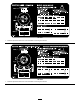
Usethechartbelowtoverifythatallpartshavebeenshipped.
ProcedureDescription
Qty.
Use
1
Towpolekit(soldseparately)
1
Installthetowpole(side-dumpmodels
only).
Tongue1
Frontstabilizerleg1
Shortbolt
6
Longbolt1
2
Nut
7
Installthetongue(end-dumpmodels
only).
Safetychain
1
3
Connectinglink
2
Installthesafetychain.
1
InstallingtheTowPole
Side-DumpModelsOnly
Partsneededforthisprocedure:
1
Towpolekit(soldseparately)
InstallingtheTowPoletotheMachine
Note:Thetowpoleispurchasedseparatelyandincludesthe
nutandboltneededforinstallation.
Themachinehasthefollowingtowpoleoptions:
HitchTypeLength
50mm(2inch)ball—stamped78.7cm(31inches)or127cm
(50inches)
50mm(2inch)ball—forged78.7cm(31inches)or127cm
(50inches)
Pintle
78.7cm(31inches)or127cm
(50inches)
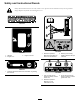
1.Removetheboltandnutfromthetowpole(Figure4).
5
1
2
4
6
3
G019804
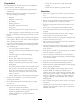
Figure4
1.Towpole4.Bolthole
2.Frontpost
5.Frametting
3.Bolt6.Nut
2.Slidethetowpoleforwardandaligntheholeinthe
polewiththeholeintheframetting(Figure4).
3.Inserttheboltthroughtheholesinthettingandthe
pole(Figure4).
4.Threadthenutontotheboltandtightenthemuntil
theyaretightagainsttheframetting(Figure4).
Note:Iftheself-lockingnyloninsertinthelocknut
wearswithuse,replacethenutwithanewGrade5or
Grade8locknut.
10