Form No. 3378-148 Rev B CM-658H-S, CM-958H-S, CM-958H-SED, CM-958H-PED, and CM-958H-P Concrete Mixers Model No. 68004—Serial No. 313000001 and Up Model No. 68006—Serial No. 313000001 and Up Model No. 68007—Serial No. 313000001 and Up Model No. 68008—Serial No. 313000001 and Up Model No. 68009—Serial No. 313000001 and Up G019544 Register at www.Toro.com.
You may contact Toro directly at www.Toro.com for product and accessory information, help finding a dealer, or to register your product. WARNING CALIFORNIA Proposition 65 Warning Whenever you need service, genuine Toro parts, or additional information, contact an Authorized Service Dealer or Toro Customer Service and have the model and serial numbers of your product ready. Write the numbers in the space provided.
Contents Introduction .................................................................. 2 Safety ........................................................................... 4 Safe Operating Practices........................................... 4 Safety and Instructional Decals ................................. 7 Setup ............................................................................ 9 1 Installing the Tow Pole—Models 68004, 68006, and 68009 ........................................................
Safety • Never let children or untrained people operate or service the equipment. Local regulations may restrict the age of the operator. Improperly using or maintaining the machine can result in injury. To reduce the potential for injury, comply with these safety instructions and always pay attention to the safety alert symbol , which means: Caution, Warning, or Danger—personal safety instruction. Failure to comply with the instruction may result in personal injury or death.
Preparation – Ensure that the lug nuts are tight and torqued properly. Become familiar with the safe operation of the equipment, operator controls, and safety signs. • Use only accessories and attachments approved by the manufacturer.
Maintenance and Storage • Before performing maintenance, do the following: – Park the machine on level ground. – Stop the engine. Wait for all movement to stop before adjusting, cleaning, or repairing. – Let the engine cool before performing maintenance or storing. – Disengage all power and operation controls. • Never lubricate, service, repair, or adjust the machine while it is running. • Keep equipment materials clear from the muffler and engine to help prevent fires. Clean up any oil or fuel spillage.
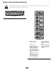
Safety and Instructional Decals Safety decals and instructions are easily visible to the operator and are located near any area of potential danger. Replace any decal that is damaged or lost. 117–2718 125–4939 1. Warning—read the Operator’s Manual. 4. Toxic gas inhalation hazard—Don’t run the engine in an enclosed space. 2.
125–4940 1. Warning 3. Engine—stop 2. Engine—run 125–8175 1. Read the Operator’s Manual for information on greasing the machine. 125–8216 1. Read the Operator’s Manual for information on how to tow the machine. 2. Warning—limit towing speed to less than 55 mph / 88 km/h.
Setup Loose Parts Use the chart below to verify that all parts have been shipped. Procedure 1 2 3 Description Use Qty. Tow pole kit (sold separately) 1 Tongue Front stabilizer leg Short bolt Long bolt Nut Safety chain Connecting link 1 1 6 1 7 1 2 1 1 Install the tow pole. Install the tongue. Install the safety chain.
2 Installing the Tongue—Models 68007 and 68008 1 Parts needed for this procedure: 1 G021092 Tongue 1 Front stabilizer leg 6 Short bolt 1 Long bolt 7 Nut Figure 6 1. Front stabilizer leg 4. Install the tongue into the opening at the front of the machine, and secure it with 6 nuts and short bolts torqued to 102 N-m (75 ft-lb); refer to Figure 7. Installing the Tongue to the Machine 1 2 3 1. Lower the rear stabilizer legs; refer to Lowering the Stabilizer Legs (page 20). 2.
Models 68007 and 68008 (End-dump) 3 1. Form a hook on the end of a bendable piece of rod or stiff wire (not included) and insert it through both keyholes in the tongue of the machine (Figure 9). Installing the Safety Chain A 1 Parts needed for this procedure: 1 Safety chain 2 Connecting link B 2 3 Models 68004, 68006, and 68009 (Side-dump) C D 1.
Product Overview 5 3 6 4 2 1 7 3 4 2 8 1 11 8 7 6 11 5 G019730 Figure 10 Models 68004, 68006, and 68009 1. Engine cowl 5. Tow pole 2. Engine switch 6. Safety-chain keyholes 3. Drum 4. Handwheel 7. Drum-tilt brake 8. Rubber latch 10 12 9 G019914 Figure 11 Models 68007 and 68008 1. Tongue-mounted tow coupler 7. Handwheel 2. Safety-chain keyholes 8. Drum-tilt brake 3. Rubber latch 4. Engine switch 12 9. Front stabilizer leg 10. Rearward pin hole 5. Engine cowl 11.
Controls 1 3 2 Become familiar with all of the controls before you start the engine and operate the machine. Engine Switch When the engine switch on the cowl is in the Run position, it allows the engine to run. Moving the engine switch to the Stop position stops the engine. Handwheel The handwheel controls the discharging action of the drum. G018792 Drum-tilt Brake Figure 13 The drum-tilt brake locks the drum into an upright position or a discharging position. 1. Fuel valve 2. Choke lever 3.
Recoil-start Handle Oil-level Switch To start the engine, pull the recoil-start handle (Figure 12) quickly to turn the engine over. The engine controls described above must all be set correctly for the engine to start. The oil-level switch is located inside the engine, and it will not allow the engine to run in the event the oil level is below the safe operating limit. Specifications Note: Specifications and design are subject to change without notice.
1 G020836 Figure 17 1. Example of tire wear caused by underinflation 2 G019733 Figure 16 Drum-Tilt Brake 1. Unlocked position 2. Locked position Figure 18 1. Example of tire wear caused by overinflation 4. Ensure the engine cowl is closed and latched; refer to Closing the Cowl (page 21). 2. Ensure that the tires are inflated to the correct air pressure. The following Tire Air Pressure table shows the appropriate air pressure for the tires as installed at the factory. 5.
7. Pull the clevis pin out from the front stabilizer leg and the tongue (Figure 21). 1 3 3 4 2 G021 107 Figure 19 2 1 Raising the Stabilizer Legs (Models 68007 and 68008) G019915 Models 68007 and 68008 have a front stabilizer leg and 2 rear stabilizer legs. Figure 21 1. Remove the clevis pin. Raise the stabilizer legs before towing the machine. 3. Install the clevis pin. 2. Rotate the stabilizer leg up. 1. Adjust the machine so that there is no weight resting on the rear stabilizer legs. 2.
Important: Apply thread-locking compound as needed in the future. A A 1 2 B 3 5 4 B 2 C D 1 C G019807 Figure 23 1. Coupler handle 4. Bolt 2. Coupler 5. Hitch ball 3. Clamp G020359 2. Apply chassis grease to the socket of the coupler and the area of the clamp that contacts the ball. Figure 22 1. Bail 2. Safety pin 3. Push the coupler bolt up through the coupler clamp and the coupler top, and connect the coupler handle to the bolt (Figure 23A). 4.
Hitching a Machine with a Pintle Hitch Coupler Hitching a Machine with a Pin Hitch Coupler 1. Remove the pin from the pintle hitch and open it (Figure 24). 1. Position the front of the pin hitch coupler so that it is located between the top and bottom plates of the pin/clevis receiver hitch of the tow vehicle, and ensure that the holes are aligned (Figure 25B). A 1 B 2 3 4 C D G020084 Figure 25 G019809 1. Hitch pin 3. Pin hitch coupler 2. Hairpin cotter 4. Pin/clevis receiver hitch 2.
Connecting the Safety Chains to the Tow Vehicle Important: Ensure that the chain has enough slack for turning around corners when towing the machine. 1. Pull the safety chain through the slots in the keyholes, so that the lengths on each side are equal. Note: For models 68004, 68006, and 68009, stow the excess chain inside the bottom of the front post by pushing it into the keyholes and latching the appropriate links into the keyhole slots. 2.
WARNING Towing the machine with material in the drum increases the risk of a hitch malfunction and tire failure. In addition, material could bounce out of the drum and hit other vehicles and/or people. Material in the drum increases the weight, which affects momentum and braking distance. Do not tow the machine with material in the drum. • Review and understand Safe Operating Practices (page 4). • Test the brakes of the tow vehicle before towing. • Avoid sudden starts and stops while towing the machine.
8. Push the clevis pin through the front hole in the tongue and the front stabilizer leg (Figure 30), and carefully lower the machine to the ground. 3. At the side of the machine, grasp the ring of the latch and pull it onto the latch anchor on the rear cowl. 4. Repeat step 3 on the opposite side of the machine (Figure 31). Opening and Closing the Cowl Adding Fuel Opening the Cowl • For best results, use only clean, fresh, unleaded gasoline 1.
Add the correct amount of fuel stabilizer/conditioner to the fuel, and follow the directions of the manufacturer. DANGER In certain conditions during fueling, static electricity can be released causing a spark which can ignite the fuel vapors. A fire or explosion from fuel can burn you and others and can damage property. Note: Fuel stabilizer/conditioner is most effective when mixed with fresh fuel. To minimize the chance of varnish deposits in the fuel system, use fuel stabilizer at all times.
1 30 5W - 30 / 10W - 30 0 20 40 -20 -10 0 60 10 80 20 30 100 F o 40 C o g013375 Figure 34 1. Place the machine on a flat, level surface, and stop the engine. 2. Allow the engine to cool. 3. Clean around the dipstick. 4. Remove the dipstick and wipe the end clean (Figure 35). 1 2 3 G020679 Figure 33 1. Maximum fuel level 4. Install the fuel cap securely (Figure 32). 4 5. Wipe up any fuel that may have spilled.
Starting and Stopping the Engine • To start a cold engine, move the choke lever to the Starting the Engine • To start a warm engine, move the choke lever in Closed position—all the way to the left (Figure 37); refer to Choke Lever (page 13). the Open position—all the way to the right. 1. On the engine cowl, move the engine switch to the On position (Figure 36). 5. Rotate the engine On/Off switch to the On position; refer to Engine On/Off Switch (page 13). 1 6.
Using the Machine Concrete has the following 4 basic ingredients: • Sand • Gravel • Portland cement • Water DANGER This machine is capable of amputating hands. • Stay in the operator’s position while the machine is running. • Keep all bystanders a safe distance from the machine. • Stop the machine immediately if any people or animals enter the work area. • Never place any part of your body into a position that causes an unsafe operating condition.
Dumping the Drum Note: When dumping a batch of material, leave the engine running so that the rotating drum helps dump the material. 1. Align a wheelbarrow or similar container of adequate capacity in the path of the drum opening. 2. While the drum is turning, firmly grasp the handwheel with one hand. 3. Using your other hand, pull upwards on the drum-tilt brake handle to release the brake. 4.
Maintenance Important: Before performing any maintenance procedures, first stop the engine, wait 5 minutes to allow all moving parts to come to a complete stop and cool, and disconnect the spark-plug wire. Recommended Maintenance Schedule(s) Maintenance Service Interval Maintenance Procedure After the first 25 hours • Change the engine oil. Before each use or daily • Inspect the tires and wheels. • Check the engine oil level. • Inspect the air-cleaner elements.
Removing and Installing the Divider Plate 4. Tighten the bolts with a wrench until they are secure. You need to remove the divider plate to provide access before performing some maintenance procedures. Removing the Divider Plate 1. Unlatch and open the cowl; refer to Opening the Cowl (page 21). 2. Use a wrench to remove the 4 bolts that secure the divider plate to the front cowl. Note: Keep the bolts and washers for installing the divider plate. G021094 Figure 40 3.
Lubrication Engine Maintenance Lubricating the Machine Servicing the Air Cleaner Service Interval: Before each use or daily—Inspect the air-cleaner elements. Every 50 hours—Clean the air-cleaner elements. Clean them more frequently in dusty operating conditions. Every 300 hours/Yearly (whichever comes first)—Replace the paper air-cleaner element. Replace it more frequently in dusty operating conditions. Service Interval: Monthly—Grease the trunnions and the drum spindle. 1.
4. Remove the cover. 30 Note: Be careful to prevent dirt and debris from falling into the base. 5W - 30 / 10W - 30 5. Remove the foam and paper elements from the base (Figure 43). 0 6. Remove the foam element from the paper element (Figure 43). 20 40 -20 -10 0 7. Inspect the foam and paper elements, and replace them if they are damaged or excessively dirty. 60 10 80 20 30 100 F o 40 C o g013375 Figure 44 8. If the paper element is excessively dirty, replace it.
Removing the Spark Plug 5. When the oil has drained completely, install the drain plug with a new washer (Figure 45). 1. Park the machine on a level surface and turn off the engine; refer to Stopping the Engine (page 24). Note: Dispose of the used oil at a certified recycling center. 2. Ensure that the machine surfaces are cool. 3. Pull the spark-plug wire off the terminal of the spark plug (Figure 47). Filling the Engine Crankcase with Oil 1.
Checking the Spark Plug • When installing an in-service spark plug, tighten the plug an additional 1/8 to 1/4 turn. Note: Use a gapping tool/feeler gauge to check and adjust the gap. Install a new spark plug if necessary. • When installing a new spark plug, tighten the plug an additional 1/2 turn. 1. Look at the center of the spark plug (Figure 49). If you see light brown or gray on the insulator, the engine is operating properly. 4.
Servicing the Spark Arrester Note: Replace the spark arrester if it has breaks or holes. Cleaning the Spark Arrester Service Interval: Every 100 hours Note: A spark arrester is available as an option. If you require a spark arrester, contact your Authorized Toro Service Dealer. Genuine Toro spark arresters are approved by the USDA Forestry Service. 1 G019332 Figure 51 WARNING 1. Screen If the engine has been running, the muffler will be hot. 8.
Fuel System Maintenance 9. Align the O-ring in to the groove in the sediment cup and install the sediment cup to fuel valve housing. 10. Move the lever of the fuel valve to the On position (all the way to the right) and check for leaks. If it leaks, replace the O-ring. Servicing the Fuel System Cleaning the Sediment Cup Service Interval: Every 100 hours/Every 6 months (whichever comes first)—Clean the sediment cup. Yearly or before storage—Clean the fuel sediment cup.
Belt Maintenance 3. With your finger, push on the belt with 6.8 kg (15 lb) of pressure, midway between the pulleys (Figure 53). 4. Measure the distance from the belt to the straightedge. The distance should be approximately 1 cm (13/32 inch); refer to Figure 53. If the belt tension needs adjustment, refer to Adjusting the Drive-belt Tension (page 35). Servicing the Drive Belts Service Interval: Every 20 hours—Inspect the drive-belt tension and adjust it as necessary.
Replacing the Drive Belts Cleaning Service Interval: Every 100 hours Cleaning the Machine Note: The machine has 2 drive belts. Remember to buy 2 belts for replacement. Regular cleaning and washing with mild detergent and water will increase the life span of the machine. Clean the machine after each use before the dirt hardens. 1. Complete steps 1 through 3 in Adjusting the Drive-belt Tension (page 35). 2. Slide the engine to the right to decrease the belt tension.
Storage 9. Check and tighten all bolts, nuts, and screws. Repair or replace any part that is damaged. Storing the Machine 10. Paint all scratched or bare metal surfaces with paint available from your Authorized Toro Dealer. For storage over 30 days, prepare the machine as follows: 11. Store the machine in a clean, dry garage or storage area. 1. Remove dirt and grime from the external parts of the entire machine, especially the engine.
Troubleshooting Problem The engine will not start. Possible Cause 1. The engine switch on the cowl is in the Stop position. 1. Press the engine switch to the Run position. 2. The fuel valve is in the Off position. 2. Move the fuel-valve lever to the On position. 3. Close the choke when starting a cold engine. 4. Open the choke when starting a hot engine. 5. Rotate the switch to the On position. 3. The choke is open. 4. The choke is closed. 5. The On/Off switch on the engine is in the Off position. 6.
Notes: 39
Concrete, Masonry, and Compaction Equipment The Toro Warranty A limited warranty (see warranty periods below) Conditions and Products Covered The Toro Company and its affiliate, Toro Warranty Company, pursuant to an agreement between them, jointly warrant your Toro Concrete, Masonry, and Compaction Equipment Products listed below to be free from defects in materials or workmanship. This warranty covers the cost of parts and labor, but you must pay transportation costs.