
Operator's Manual


3
InstallingtheSafetyChain
Partsneededforthisprocedure:
1
Safetychain
2
Connectinglink
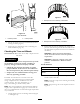
Models68004,68006,and68009
(Side-dump)
1.Formahookontheendofabendablepieceofrodor
stiffwire,(notincluded),andinsertitthroughboth
keyholesinthefrontpostofthemachine(Figure8A).
A
B
C
D
g019883
2
3
4
3
1
Figure8
1.Keyhole
3.Safetychain
2.Rodorwire(notincluded)4.Connectinglink
2.Attachthesafetychaintothelengthofrodorwire
(Figure8A).
3.Pulltherod,orwire,andthesafetychainthroughboth
keyholes(Figure8B).
Note:Ensurethatapproximatelyequallengthsof
safetychainextendfromeithersideofthefrontpost.
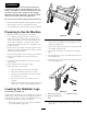
Models68007and68008(End-dump)
1.Formahookontheendofabendablepieceofrod
orstiffwire(notincluded)andinsertitthroughboth
keyholesinthetongueofthemachine(Figure9).
A
B
C
D
G019919
2
3
4
3
1
Figure9
1.Keyhole
3.Safetychain
2.Rodorwire(notincluded)4.Connectinglink
2.Attachthesafetychaintothelengthofrodorwire
(Figure9).
3.Pulltherod,orwire,andthesafetychainthroughboth
keyholes(Figure9).
Note:Ensurethatapproximatelyequallengthsof
safetychainextendfromeithersideofthetongue.
InstallingtheConnectingLinks
1.Aligntheconnectinglinktothelastlinkinoneendof
thesafetychain(Figure8DandFigure9D).
2.Inserttheconnectinglinkthroughthechainlinkuntil
theconnectinglinksnapsclosed.
3.Repeatsteps1and2toinstalltheotherconnectinglink
intheotherendofthesafetychain.
11