
Operator's Manual


G021092
1
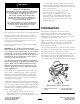
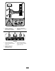
Figure6
1.Frontstabilizerleg
4.Installthetongueintotheopeningatthefrontofthe
machine,andsecureitwith6nutsandshortbolts
torquedto102N-m(75ft-lb);refertoFigure7.
1 2
3
4
5
6
G021093
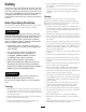
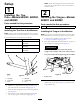
Figure7
1.Clevispin4.Nut(7)
2.Longbolt5.Tongue
3.Shortbolt(6)
6.Frontstabilizerleg
5.Alignthetoprearholeinthefrontstabilizerlegtothe
holepastthehandleinthefrontofthetongue(Figure
7).
6.Installthelongboltthroughtheholes,andsecureit
withanuttorquedto102N-m(75ft-lb);referto
Figure7.
Note:Thestabilizerlegpivotsrearwardonthebolt.
Ifyouinstalltheboltintothewronghole,thestabilizer
legwillnotworkproperly.
7.Inserttheclevispintolockthefrontstabilizerlegin
position(Figure7).
3
InstallingtheSafetyChain
Partsneededforthisprocedure:
1
Safetychain(soldwithoptionaltowpolekit)
2
Connectinglink(soldwithoptionaltowpolekit)
InstallingtheSafetyChaintothe
Machine
Note:Thesafetychainispartoftheoptionaltowpolekit.
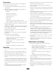
1.Formahookontheendofabendablepieceofrodor
stiffwire,(notincluded),andinsertitthroughboth
keyholesinthefrontpostofthemachine(Figure8and
Figure9).
A
B
C
D
g019883
2
3
4
3
1
Figure8
Models68004C,68006C,and68009C(Side-dump)
1.Keyhole
3.Safetychain
2.Rodorwire(notincluded)4.Connectinglink
10