Form No. 3379-761 Rev A FP-2200/3000/4000 Forward Plate Compactor Model No. 68025—Serial No. 313000001 and Up Model No. 68026—Serial No. 313000001 and Up Model No. 68027—Serial No. 313000001 and Up g019691 Register at www.Toro.com.
WARNING CALIFORNIA Proposition 65 Warning This product contains a chemical or chemicals known to the State of California to cause cancer, birth defects, or reproductive harm. The engine exhaust from this product contains chemicals known to the State of California to cause cancer, birth defects, or other reproductive harm. Use of this product may cause exposure to chemicals known to the State of California to cause cancer, birth defects, or other reproductive harm.
Contents Safety Introduction .................................................................. 2 Safety ........................................................................... 3 Safe Operating Practices........................................... 3 Safety and Instructional Decals ................................. 5 Setup ............................................................................ 6 Installing the Handle................................................ 6 Checking the Engine Oil Level ..
• Let the engine cool before storing and do not store near – Never refuel or drain the machine indoors. flame. • Check that the operator's presence controls, safety switches, and shields are attached and functioning properly. Do not operate unless they are functioning properly. • Do not store fuel near flames or drain indoors. • Park the machine on level ground. Never allow untrained personnel to service the machine.
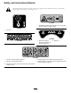
Safety and Instructional Decals Safety decals and instructions are easily visible to the operator and are located near any area of potential danger. Replace any decal that is damaged or lost. 117–4979 1. Entanglement hazard, belt—keep away from moving parts; keep all guards and shields in place 93–9084 1. Lift point 125–4945 117–2718 1. Read the Operator’s Manual for information on using the water tank. 2. Water cap 125–4943 1. Warning—read the Operator’s Manual. 4.
Setup Installing the Handle Secure each side of the handle to the plate compactor frame using a bolt, flat washer, spacer, bearing, lock washer, and nut (Figure 3 or Figure 4). 1 2 3 4 5 6 7 g019693 Figure 4 Model no. 3000/4000 Figure 3 Model no. 2200 1. Nut 1. Nut 5. Spacer 2. Lock washer 3. Bearing 6. Flat washer 7. Bolt 4. Handle 4. Spacer 2. Bearing 5. Flat washer 3. Handle 6.
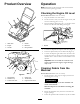
Product Overview Operation Note: Determine the left and right sides of the machine from the normal operating position. Checking the Engine Oil Level Service Interval: Before each use or daily 1. Stop the machine on a level surface. 2. Set the throttle to slow, turn off the engine switch, and wait for all moving parts to stop. 3. Clean around the dipstick (Figure 7) so that dirt cannot fall into the filler hole and damage the engine. 1 Figure 5 1. Water tank 2. Engine 4. Handle 5. Belt cover 3.
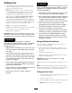
Adding Fuel DANGER • For best results, use only clean, fresh (less than 30 days When fueling, under certain circumstances, a static charge can develop, igniting the gasoline. A fire or explosion from gasoline can burn you and others and damage property. old), unleaded gasoline with an octane rating of 87 or higher ((R+M)/2 rating method). • Ethanol: Gasoline with up to 10% ethanol (gasohol) or 15% MTBE (methyl tertiary butyl ether) by volume is acceptable. Ethanol and MTBE are not the same.
1 g013315 Figure 8 g019702 Figure 10 1. Elastic tank latch 4. Add unleaded gasoline to the fuel tank, until the level is just inside the mesh filter basket. 3. Fill the tank with water, reassemble it to the frame, and reattach the coupler. Important: This space in the tank allows gasoline to expand. Do not fill the fuel tank completely full. 5. Install the fuel tank cap securely. Starting and Stopping the Engine 6. Wipe up any gasoline that may have spilled.
1 1 g019704 g019775 Figure 12 Figure 14 1. Fuel valve 1. Throttle 3. Move the choke lever to the left if you are starting a cold engine (Figure 13). 5. Pull the recoil handle sharply to start the engine. 6. After the engine starts, gradually move the choke to the right. If the engine stalls or hesitates, move the choke left again until the engine warms up. 7. Move the throttle lever to maximum throttle. Stopping the Engine 1. Move the throttle lever to the slow (turtle) position. 2.
Transporting the Machine The rollcage lifteye can be used to lift and transport the machine with straps or a crane (Figure 15). Alternatively, two people can transport the machine by lifting the compactor using the front and rear lift handles (Figure 15). 1 g019776 2 Figure 15 1. Rollcage lifteye 2.
Maintenance Recommended Maintenance Schedule(s) Maintenance Service Interval Maintenance Procedure After the first 25 hours • Change the engine oil. Before each use or daily • Check the engine oil level. • Clean debris from the air cleaner. • Inspect the air cleaner elements. Every 50 hours • Clean the air filter elements. Clean them more frequently in dusty operating conditions. Every 100 hours • Change the engine oil. • Inspect, clean, and adjust the spark plug; replace it if necessary.
4. Remove the cover. 5. 6. 7. 8. Every 100 hours Note: Be careful to prevent dirt and debris from falling into the base. Remove the foam and paper elements from the base (Figure 17). Remove the foam element from the paper element (Figure 17). Inspect the foam and paper elements, and replace them if they are damaged or excessively dirty. If the paper element is excessively dirty, replace it. WARNING Oil may be hot after the engine has been run, and contact with hot oil can cause severe personal injury.
3. Move the fuel shut-off valve to the Off position. 4. Remove the sediment cup and O-ring (Figure 6). 5. Wash the sediment cup in a nonflammable solvent and dry it thoroughly. 6. Place the O-ring in the fuel valve and install the sediment cup, tightening it securely. 7. Move the fuel shut-off lever to the On position. If any fuel leaks, repeat this procedure and replace the O-ring. Figure 20 1. Oil plug Servicing the Belt 2. Eccentric oil filler hole Adjusting the Belt 3.
Storage 3. Loosen or tighten the puller bolt on the rear of the engine deck until the desired tension is obtained. 4. Replace the belt cover and the four engine mounting bolts. 1. Stop the engine, and disconnect the spark plug wire. 2. Remove dirt and grime from the entire machine. Important: You can wash the machine with mild detergent and water. Do not pressure wash the machine. Avoid excessive use of water, especially near the engine.
Troubleshooting Problem The engine will not start, starts hard, or fails to keep running. Possible Cause Corrective Action 1. The fuel tank is empty. 1. Fill the fuel tank with gasoline. 2. The spark plug is pitted, fouled, or the gap is incorrect. 3. The air cleaner is dirty. 2. Install a new, correctly gapped spark plug. 3. Clean or replace the air cleaner elements. 1. The oil level in the eccentric housing is too high. 1. Check the oil level and drain as necessary. 2. The belt is loose. 2.
Notes: 17
Notes: 18
Notes: 19
Concrete, Masonry, and Compaction Equipment The Toro Warranty A limited warranty (see warranty periods below) Conditions and Products Covered The Toro Company and its affiliate, Toro Warranty Company, pursuant to an agreement between them, jointly warrant your Toro Concrete, Masonry, and Compaction Equipment Products listed below to be free from defects in materials or workmanship. This warranty covers the cost of parts and labor, but you must pay transportation costs.