Form No. 3421-187 Rev A FP-2200 Forward Plate Compactor Model No. 68025—Serial No. 402300000 and Up Model No. 68026—Serial No. 402300000 and Up Model No. 68027—Serial No. 402300000 and Up Register at www.Toro.com.
WARNING CALIFORNIA Proposition 65 Warning This product contains a chemical or chemicals known to the State of California to cause cancer, birth defects, or reproductive harm. The engine exhaust from this product contains chemicals known to the State of California to cause cancer, birth defects, or other reproductive harm. This engine is not equipped with a spark arrester muffler.
Contents Safety Safety ....................................................................... 3 Safe Operating Practices.................................... 3 Safety and Instructional Decals .......................... 5 Setup ........................................................................ 6 Installing the Handle ........................................... 6 Checking the Engine-Oil Level............................ 6 Checking the Eccentric-Oil Level ........................ 6 Product Overview ...
– Use only an approved container Maintenance and Storage – Do not remove the fuel cap or fill the fuel tank while the engine is running or hot. • Let the engine cool before storing and do not store – Do not add or drain fuel in an enclosed space. • Position the machine on a level surface, set the the machine near an open flame. throttle to slow, and shut off the engine. Wait for all movement to stop before adjusting, cleaning, or repairing.
Safety and Instructional Decals Safety decals and instructions are easily visible to the operator and are located near any area of potential danger. Replace any decal that is damaged or missing. decal133-5619 133-5619 decal93-9084 93-9084 1. Lift point decal117-4979 117-4979 1. Entanglement hazard, belt—keep away from moving parts; keep all guards and shields in place decal125-4943 125-4943 1. Warning—read the Operator’s Manual. 4. Choking hazard—do not operate the machine indoors. 2.
Setup Installing the Handle Secure each side of the handle to the plate compactor frame using a bolt, flat washer, spacer, bearing, and locknut (Figure 3 or Figure 4). g027147 Figure 4 Model 3000/4000 g019697 Figure 3 Model 2200 1. Locknut 4. Spacer 2. Bearing 5. Flat washer 3. Handle 6. Bolt 1. Locknut 4. Spacer 2. Bearing 5. Flat washer 3. Handle 6.
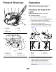
Product Overview Operation Note: Determine the left and right sides of the machine from the normal operating position. Checking the Engine-Oil Level Service Interval: Before each use or daily Oil crankcase capacity: • 0.56 L (0.59 US qt) for Model 68025 • 0.58 L (0.61 US qt) for Models 68026 and 68027 g027691 1. Position the machine on a level surface. 2. Set the throttle to slow, shut off the engine, and wait for all moving parts to stop. 3.
Important: Running the engine with a low oil level can cause engine damage. This type of damage is not covered by warranty. The engine is equipped with an oil alert system that will automatically shut off the engine before the oil level falls below the safe limit. 7. • Do not store fuel either in the fuel tank or fuel containers over the winter unless a fuel stabilizer is used. • Do not add oil to gasoline. DANGER In certain conditions, fuel is extremely flammable and highly explosive.
Add the correct amount of gas stabilizer/conditioner to the gas. DANGER In certain conditions during fueling, static electricity can be released causing a spark which can ignite the fuel vapors. A fire or explosion from fuel can burn you and others and can damage property. Note: A fuel stabilizer/conditioner is most effective when mixed with fresh fuel. To minimize the chance of varnish deposits in the fuel system, use fuel stabilizer at all times.
Adding Water with the Tank Removed Compacting Asphalt When using the machine on asphalt, the water system is used to wet the surface of the compactor to prevent the asphalt from sticking to the compactor. 1. Detach the valve coupler (Figure 10). Adding Water with the Tank Installed 1. Remove the cap from the water tank (Figure 9). g024875 Figure 10 g024848 Figure 9 1. Water-tank cap 3. Water tank 1. Shutoff valve 3. Male coupler 2. Female coupler 4. Sprinkler manifold 2. Water 2. 2.
Starting the Engine 1. Move the engine switch to the ON position (Figure 12). g019774 Figure 14 1. Choke g019703 4. Figure 12 1. Engine switch Move the throttle lever midway between the SLOW (turtle) and FAST (rabbit) positions (Figure 15). Note: A warm or hot engine may not require 2. Move the fuel valve to the ON position (Figure 13). choking. g019775 Figure 15 g019704 Figure 13 1. Throttle 1. Fuel valve 3. Move the choke lever to the left if you are starting a cold engine (Figure 14).
Important: If the engine stalls or hesitates, move the choke left again until the engine warms up. 7. Move the throttle lever to maximum throttle. Shutting Off the Engine 1. Move the throttle lever to the SLOW (turtle) position. 2. Turn the engine switch and fuel valve off. Operating the Compactor With the engine at full throttle, the compactor moves forward while vibrating. Grasp the handle lightly with both hands and allow the compactor to move forward on its own.
Maintenance Recommended Maintenance Schedule(s) Maintenance Service Interval Maintenance Procedure After the first 25 hours • Change the engine oil. Before each use or daily • Check the engine-oil level. • Clean debris from the air cleaner. • Inspect the air-cleaner elements. Every 50 hours • Clean the air-filter elements. Clean them more frequently in dusty operating conditions. Every 100 hours • • • • Every 200 hours • Replace the spark plug.
r:\g000533 Figure 18 1. Center electrode insulator 2. Side electrode 3. Air gap (not to scale) 6. 7. Carefully install the spark plug by hand (to avoid cross threading) until it is hand tight. g027313 Figure 19 Tighten the spark plug an additional 1/2 turn if it is new; otherwise, tighten it an additional 1/8 to 1/4 turn. 1. Wing nut (cover) Important: A loose spark plug can become very hot and can damage the engine; overtightening a spark plug may damage the threads in the cylinder head. 8. 5.
2. 3. 4. Allow the foam filter element to completely dry. Dip the foam element in clean engine oil, then squeeze out the excess oil. 1. Shut off the engine and wait for all moving parts to stop. 2. Disconnect the wire from the spark plug. Note: If too much oil is left in the foam element 3. Move the fuel-shutoff valve to the OFF position. 4. Remove the sediment cup and O-ring (Figure 6). when the engine is started, the engine will smoke.
Servicing the Engine Oil Oil Type: Detergent oil (API service SJ or higher) Oil crankcase capacity: • 0.56 L (0.59 US qt) for Model 68025 • 0.58 L (0.61 US qt) for Models 68026 and 68027 Viscosity: See table below g019692 Figure 22 1. Drain plug Note: You may have to tip the compactor backwards to drain the oil. g013375 Figure 21 4. Note: Dispose of the used oil at a certified recycling center. Changing the Engine Oil Service Interval: After the first 25 hours 5.
Servicing the Eccentric Oil Changing the Eccentric Oil Oil type: 10W30 (API service SJ or higher) Service Interval: Every 300 hours Oil capacity: • 1.3 L (1.4 US qt) for Model 68025 • 3.3 L (3.5 US qt) for Model 68026 1. Set the throttle to slow, shut off the engine, and wait for all moving parts to stop. 2. Place an oil drain pan under the oil plug and remove the fill plug and the oil plug screw (Figure 23). 3.
Belt Maintenance Checking the Belt Tension Service Interval: Every 100 hours Removing the Belt Cover 1. Important: The best belt tension for the machine is the lowest tension at which the belts do not slip under full power. Remove the flanged-head bolts that secure the belt cover to the engine (Figure 24 or Figure 25). 1. Lay a straight edge on the belt and across the pulleys (Figure 26). g027329 Figure 24 Model 2200 g024879 1. Bolt locations Figure 26 2. Flanged-head bolt 1. Straight edge 2.
Adjusting the Belt Tension 1. Remove the water tank; refer to Adding Water with the Tank Removed (page 10). 2. Loosen the 2 hex-socket bolts (5/16-24 x 1.75 inches) that secure the front of the engine (Figure 27). g024877 Figure 27 1. Hex-socket bolts (5/16-24 x 1.75 inches) 3. Loosen the 2 flange nuts (8 mm) that secure the back of the engine (Figure 28). g024878 Figure 28 1. Flange nuts (8 mm) 2. Belt-tensioning bolt 4.
Storage 1. Shut off the engine and disconnect the spark-plug wire from the spark plug. 2. Remove dirt and grime from the entire machine. Important: You can wash the machine with mild detergent and water. Do not pressure wash the machine. Avoid excessive use of water, especially near the engine. 3. Service the air cleaner; refer to Servicing the Air Cleaner (page 14). 4. Change the engine oil; refer to Changing the Engine Oil (page 16). 5. For storage over 30 days, prepare the unit as follows: A.
Troubleshooting Problem The engine does not start, starts hard, or fails to keep running. The plate does not vibrate at full speed. The clutch is extremely hot. The plate does not vibrate when the engine is running. There is insufficient water flow. Possible Cause Corrective Action 1. The fuel tank is empty. 1. Fill the fuel tank with fuel. 2. The spark plug is pitted, fouled, or the gap is incorrect. 3. The air cleaner is dirty. 2. Install a new, correctly gapped spark plug. 3.
Notes:
Notes:
California Proposition 65 Warning Information What is this warning? You may see a product for sale that has a warning label like the following: WARNING: Cancer and Reproductive Harm—www.p65Warnings.ca.gov. What is Prop 65? Prop 65 applies to any company operating in California, selling products in California, or manufacturing products that may be sold in or brought into California.