
Operator's Manual

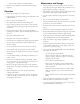


ProductOverview
Figure5
1.Watertank5.Handle
2.Engine6.Beltcover
3.Rollcagelifteye7.Lifthandles
4.Airlter
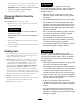
Figure6
1.Recoilstarter
4.Chokelever
2.Sedimentcup
5.Throttlelever
3.Fuel-shutoffvalve6.EngineOn/Offswitch
Operation
Note:Determinetheleftandrightsidesofthemachine
fromthenormaloperatingposition.
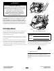
CheckingtheEngine-oilLevel
ServiceInterval:Beforeeachuseordaily
Oilcrankcasecapacity:
•0.56L(0.59USqt)forModel68025
•0.58L(0.61USqt)forModels68026and68027
1.Stopthemachineonalevelsurface.
2.Setthethrottletoslow,turnofftheengineswitch,and
waitforallmovingpartstostop.
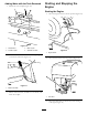
3.Cleanaroundthedipstick,sothatdirtcannotfallinto
thellerholeanddamagetheengine(Figure7).
1
2
3
4
g019686
5
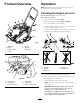
Figure7
1.Fillertube4.Lowerlimit
2.Dipstick
5.Oil-drainbolt
3.Upperlimit
4.Removethedipstickandwipetheendclean.
5.Slidethedipstickfullyintothedipsticktubewithout
threadingitintothellerneck.
6.Pullthedipstickoutandlookattheend.
Note:Theoilshouldbelevelwiththeupper-limit
mark(Figure7).
Important:Runningtheenginewithalowoil
levelcancauseenginedamage.Thistypeof
damageisnotcoveredbywarranty.
Theengineisequippedwithanoilalertsystem
thatwillautomaticallystoptheenginebeforethe
oillevelfallsbelowthesafelimit.
7