
Operator's Manual


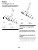


ProductOverview
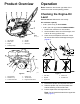
g027691
Figure5
1.Lifthandles5.Airlter
2.Watertank6.Handle
3.Engine7.Beltcover
4.Rollcagelifteye
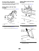
g013311
Figure6
1.Recoilstarter
4.Chokelever
2.Sedimentcup
5.Throttlelever
3.Fuel-shutoffvalve6.EngineOn/Offswitch
Operation
Note:Determinetheleftandrightsidesofthe
machinefromthenormaloperatingposition.
CheckingtheEngine-Oil
Level
ServiceInterval:Beforeeachuseordaily
Oilcrankcasecapacity:
•0.56L(0.59USqt)forModel68025
•0.58L(0.61USqt)forModels68026and68027
1.Positionthemachineonalevelsurface.
2.Setthethrottletoslow,shutofftheengine,and
waitforallmovingpartstostop.
3.Cleanaroundthedipsticksothatdirtcannot
fallintothellerholeanddamagetheengine
(Figure7).
g019686
Figure7
1.Fillertube4.Lowerlimit
2.Dipstick
5.Oil-drainbolt
3.Upperlimit
4.Removethedipstickandwipetheendclean.
5.Slidethedipstickfullyintothedipsticktube
withoutthreadingitintothellerneck.
6.Pullthedipstickoutandinspecttheend.
Note:Theoilshouldbelevelwiththeupper-limit
mark(Figure7).
7